Ford 3000 Ignition Switch Wiring Diagram – First, we will examine the various types of terminals that are found in the ignition switch. These are the terminals that connect the Ignition, Coil, or Accessory. Once we have established what these kinds of terminals are then we can identify the different parts of the Ford 3000 Ignition Switch Wiring Diagram. We will also cover the functions of both the Ignition Switch and the Coil. We’ll then turn our attention to the accessory terminals.
Terminals for ignition switch
There are three separate switches on an ignition switch that transmit the battery’s current voltage to various destinations. The first one supplies power to the choke when it is pushed. The second is the ignition switch’s ON/OFF position. Different manufacturers have different colors-coding systems to match the conductors. OMC employs this system. A tachometer adapter is installed on the ignition switch to allow the installation of an tachometer.
While the majority of ignition switch terminals don’t have the original design, the numbering may not match the diagram. Before plugging into the ignition switch, make sure to check the continuity. This can be done with a multimeter that is inexpensive. When you’re satisfied that all wires are running in good harmony, you can attach the new connector. If your vehicle has an original ignition switch supplied by the factory (or wiring loom), the wiring loom might differ from that of the car.
The first step is to understand the distinctions between ACC and the auxiliary outputs. The ACC and IGN connectors are the default connections of your ignition switch. Although the START, IGN, and ACC terminals are primary connections for the radio or stereo, the START/IGN terminals are the most important ones. The ignition switch’s function is for turning the car’s engine on and off. The ignition switch terminals on older vehicles are marked with the alphabets “ACC” as well as “ST” (for the individual magneto wires).
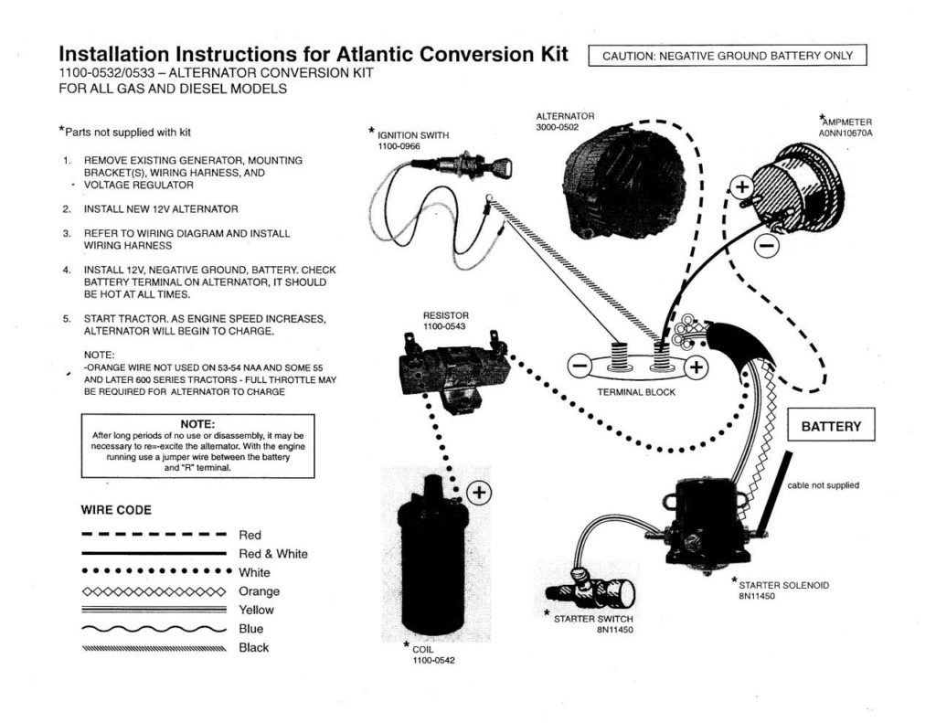
Terminals for coil
Understanding the terms is the first step to determining which type of ignition coil you own. In a simple ignition wiring diagram there are various connections and terminals, which include two primary and two secondary. The coils come with a distinct operating voltage. The first step to determine which one you have will involve testing the voltage on S1, the main terminal. S1 should be checked for resistance to identify if the coil is Type A, B, and/or C.
The low-tension side of the coil needs to be connected to the chassis”negative. This is also the ground on the wiring diagram for ignition. The high-tension side provides the spark plugs with positive. To reduce the noise the coil’s body metal is required to be connected to the chassis. This is not necessary for electrical use. The wiring diagram for the ignition will explain how to connect the two terminals of the positive and negative coils. Sometimes, a damaged ignition coil can be detected with a scan in an auto parts shop.
The black-and-white-striped wire from the harness goes to the negative terminal. The white wire has a black color and connects to the negative terminal. The contact breaker is attached to the black wire. To check the connections, use a paperclip or a pencil to remove them from the plug housing. Be sure to check that the terminals aren’t bent.
Accessory Terminals
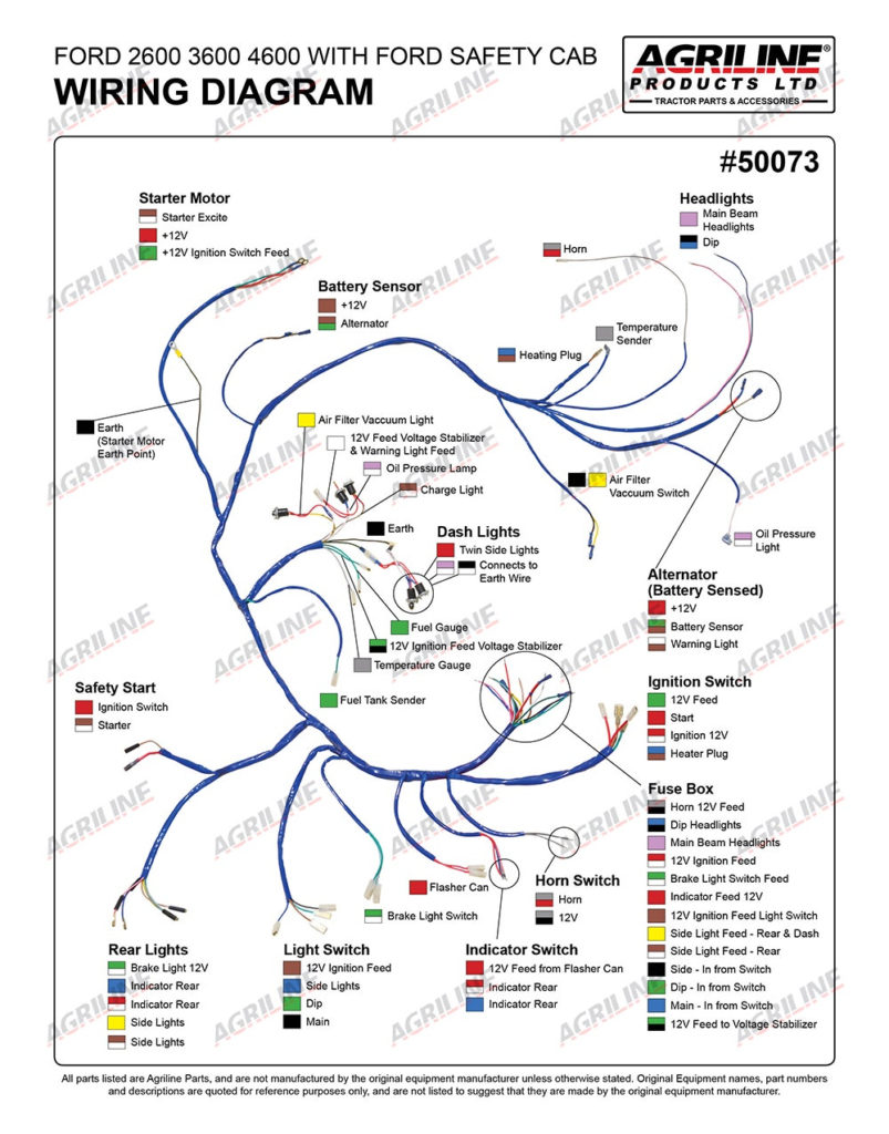
Diagrams of the ignition wiring illustrate the wires used to provide power to various components of the car. There are usually four color-coded terminus for each component. To identify accessories, red is the starter solenoid’s color, yellow for battery and blue for accessories. The “IGN terminal” is used to run the wipers, along with other operational functions. The diagram below illustrates how to connect the ACC terminal and ST terminals to the other components.
The terminal known as BAT is the place where the battery is. Without the battery the electrical system will not start. A dead battery can cause the switch to not turn on. The wiring diagram will inform the location of your car’s battery. The accessory terminals on your car connect to the battery as well as the ignition switch. The BAT terminal connects to the battery.
Certain ignition switches come with an accessory position where users can adjust their outputs and control them without the need to use the ignition. Some customers may prefer to use the auxiliary output independently of the ignition. The auxiliary output is used to connect the connector with the same color as your ignition, and then connecting it to the ACC terminal of the switch. Although this is a useful feature, there’s one significant difference. The majority of ignition switches are set to operate in the ACC position when the car is in the ACC position, but they’re set to the START position when the car is in the IGN position.
Gallery of Ford 3000 Ignition Switch Wiring Diagram
Gallery of Ford 3000 Ignition Switch Wiring Diagram


