Ford 3600 Tractor Ignition Switch Wiring Diagram – We’ll begin by looking at different types of terminals on the ignition switch. They include terminals for the Ignition switch, Coil, and Accessory. Once we know the terminals that are utilized and which ones are not, we can determine the various components of the Ford 3600 Tractor Ignition Switch Wiring Diagram. We’ll also go over the roles of the Ignition switch, as well as the Coil. Following that, we will proceed to the Accessory Terminals.
The terminals of the ignition switch
An ignition switch is comprised of three switches. They transmit the voltage of the battery to different places. The ON/OFF setting of the switch that controls the ignition is managed by the second switch, which supplies power to the choke whenever it’s pushed. Different manufacturers have different color-coding systems for different conductors. We will cover this in another article. OMC utilizes this method. An additional connector is included inside the ignition switch to allow attaching a Tachometer.
Although the majority of ignition switch terminals aren’t original, the numbering for each one may not be in line with the diagram. Check the continuity of all wires to make sure they’re properly plugged into the ignition switches. A multimeter that is inexpensive can help you do this. When you’re satisfied that all wires are running in good harmony, you can attach the new connector. If your vehicle has an original ignition switch supplied by the factory (or wiring loom), the wiring loom will differ from that in your car.
It is essential to know how the ACC outputs and the auxiliary outputs work in order to connect them. The ACC/IGN connections function as the default connection on the ignition switch. The START/IGN terminals are connected to the stereo or radio. The ignition switch is responsible for turning the engine of your car to and off. Older cars are identified by the initials “ACC”, “ST”, (for individual magneto cables) at their ignition switch terminals.
Terminals for coil
The first step in determining the kind of ignition coil is to understand the terms that is used. In a simple diagram of the wiring for ignition you’ll see a number of different connections and terminals, such as two primary and two secondary. The operating voltage of each coil is different. This is why it is crucial to test the voltage at the S1 (primary terminal). S1 must be checked for resistance to determine if the coil is Type A, B, and/or C.
The lower-tension side of the coil must be connected to the chassis”negative. This is the ground in the ignition wiring diagram. The high tension part supplies positive directly the spark plugs. It is essential for the purpose of suppression that the metallic body of the coil is connected to its chassis, however it isn’t essential. A wiring diagram can also show the connection between the positive and negative coils. There could be an issue with your ignition coil that is easily identified by looking it up at the auto parts shop.
The black-and-white-striped wire from the harness goes to the negative terminal. The other white wire has a black color and goes to the terminal opposite. The black wire is connected to the contact breaker. To test the wires’ connections use a paperclip to remove them from the housing. Make sure that the connectors aren’t bent.
Accessory Terminals
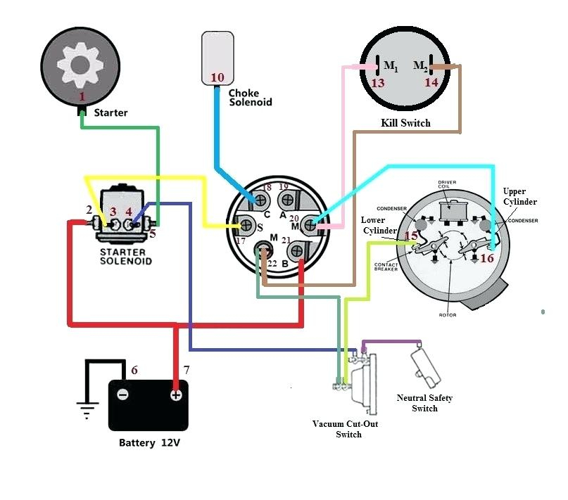
Diagrams of the ignition wiring illustrate the wires that supply power to different parts of the car. There are generally four colored terminals that correspond to the respective component. The red color is used for accessories, yellow is for the battery, and green is for the solenoid for starters. The “IGN” terminal is used to turn on the car and operate the wipers, as well as other operating functions. This diagram shows how you can connect ACC and ST terminals to the rest of the components.
The battery is connected to the terminal called BAT. The electrical system is not able to begin without the battery. Also, the switch won’t be able to turn on without the battery. The wiring diagram will show you the location of your car’s battery. The accessory terminals of your car connect to the ignition switch and the battery. The BAT terminal is connected to the battery.
Some ignition switches come with an independent “accessory” position, in which users can manage their outputs without using the ignition. In some cases, users may want to utilize the auxiliary input separately from the ignition. In order for the auxiliary output be used, plug in the connector in the same shade as the ignition. Connect it to the ACC end of the switch. This is an excellent feature, however there’s an important difference. A majority of ignition switches feature the ACC position when your vehicle is in the ACC mode and a START mode when it is in IGN.
Gallery of Ford 3600 Tractor Ignition Switch Wiring Diagram
Gallery of Ford 3600 Tractor Ignition Switch Wiring Diagram


