Ford Pinto Ignition Wiring Diagram – Let’s begin by examining the different types and functions of the terminals found in the ignition switches. These terminals include the Ignition switch as well as the Coil along with the Accessory. After we’ve identified which terminals are used and which ones are not, we can recognize the various parts of the Ford Pinto Ignition Wiring Diagram. We will also cover the roles of both the Ignition Switch and the Coil. After that, we’ll turn our attention to the Accessory terminals.
Terminals for the ignition switch
An ignition switch is composed of three different switches. They are responsible for feeding the battery’s power to several locations. The first switch provides power to the choke, and the third switch toggles the on/off status of the ignition switch. Different manufacturers use different color-coding methods for different conductors. This will be covered in a separate article. OMC uses the same method. The adapter is attached to the ignition switch to allow for the addition of a Tachometer.
Although the majority of ignition switch terminals are duplicated, the numbers may not be in line with the diagram. First, check the continuity of all wires to ensure they are correctly connected to the ignition switches. This can be done with a simple multimeter. After you’re sure that all wires are in good order, you can attach the new connector. The wiring loom of an ignition system switch that is supplied by the manufacturer is distinct.
For connecting the ACC outputs to the auxiliary outputs of your car, you’ll need to first understand how these two connections work. The ACC and IGN connectors are the default connections for your ignition switch. Although the START, IGN, and ACC terminals are the primary connections to the radio or stereo, the START/IGN connections are the primary ones. The ignition switch’s function is for turning the car’s engine on and off. The terminals of older cars’ ignition switches are labeled with “ACC” as well as ST (for individual magneto wires).
Terminals for coil
To identify the kind of ignition coil, the first step is to know the terms. The diagram of the basic ignition wiring shows a number different connections and terminals. There are two primary and secondary connections. Each coil is equipped with a distinct operating voltage. To determine what kind of coil you own the first step is to check the voltage at S1, the primary terminal. S1 must also go through resistance testing to determine if it’s an A or B coil.
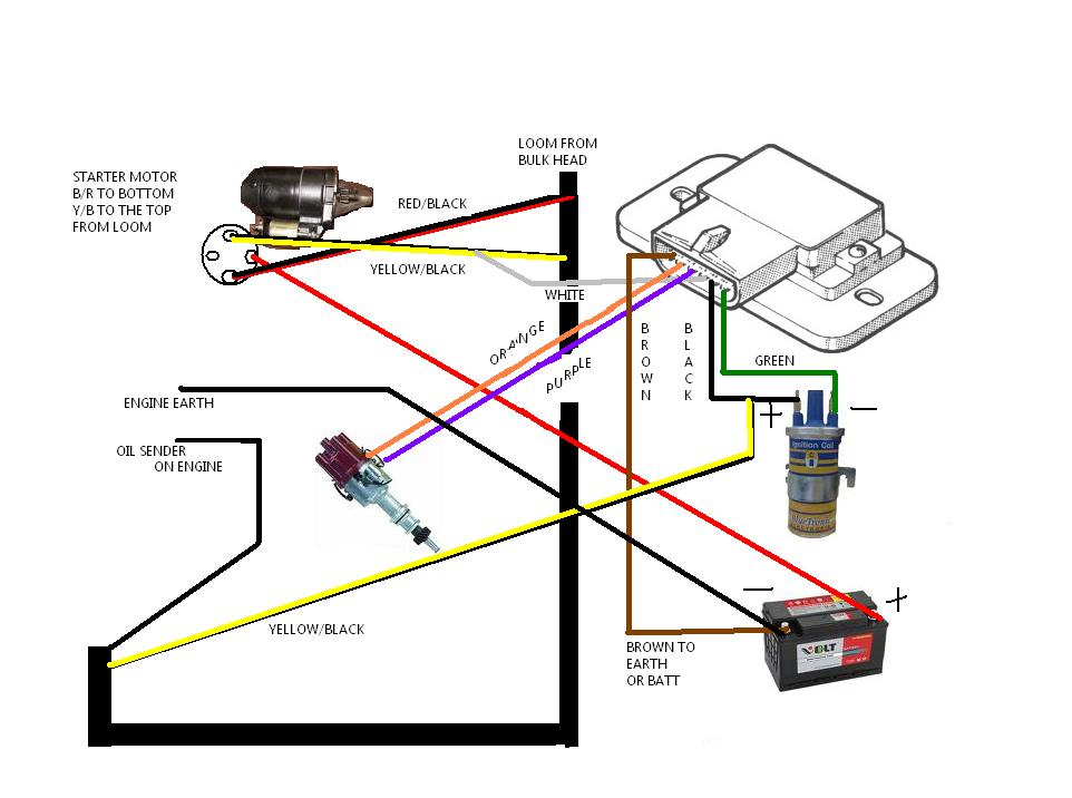
The lower-tension side of the coil must be connected to the chassis”negative. It is also the ground in the diagram of ignition wiring. The high tension side supplies positively directly to the spark plugs. The metal body of the coil needs to be connected to the chassis to prevent it from being smothered but is not electrically essential. The wiring diagram of the ignition will demonstrate how to connect the terminals of either the positive or negative coils. In certain cases scanning your local auto parts store will be able to diagnose the malfunctioning ignition coils.
The black-and-white-striped wire from the harness goes to the negative terminal. The positive terminal is connected to the white wire with an trace in black. The contact breaker is connected to the black wire. It is possible to check the connections using a paperclip to take the wires out from the housing. Make sure that the connectors don’t bend.
Accessory terminals
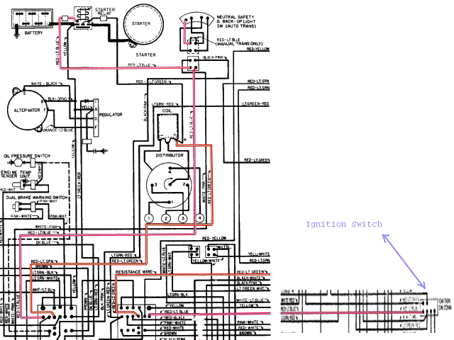
The wiring diagrams of the ignition illustrate the different wires that are used to power various components of the car. Typically there are four distinct color-coded terminals for each component. The red symbol represents accessories, yellow represents the battery and green is for the solenoid for starters. The “IGN terminal lets you start the car, manage the wipers or other operation features. The diagram shows how to connect ACC or ST terminals and the rest.
The terminal called BAT is where the battery is connected. The electrical system will not start in the event that the battery isn’t connected. A dead battery could make the switch not turn on. A wiring diagram can tell you where to find your car’s battery. The ignition switch is connected to the battery of your car. The BAT Terminal is connected to the Battery.
Certain ignition switches have a separate “accessory” location, which allows users can control their outputs without using the ignition. Some customers might want to use the auxiliary input independently of the ignition. The auxiliary output could be connected to connect the connector with the same colors as your ignition, and then attaching it to the ACC terminal of the switch. This option is useful however it does have one major distinction. Many ignition switches have an ACC position when your car is in ACC mode and a START mode when the switch is in IGN.
Gallery of Ford Pinto Ignition Wiring Diagram
Gallery of Ford Pinto Ignition Wiring Diagram


