Gas Club Car Ignition Switch Wiring Diagram – In the beginning, we’ll look at the different types of terminals found on the ignition switch. They are the terminals used that are used for Coil, Ignition Switch, and Accessory. After we’ve established the purpose of these terminals are for then we can determine the various parts of the Gas Club Car Ignition Switch Wiring Diagram. We’ll also be discussing the function of the Ignition switch, and Coil. Next, we’ll discuss the functions of the Ignition switch and Coil.
Terminals of ignition switch
The ignition switch is comprised of three switches that supply the battery’s current to different locations. The choke is powered by the first switch. The second switch controls the ON/OFF switch of the ignition switch. Different manufacturers have different color codes for various conductors. This is explained in a different article. OMC utilizes this method. The ignition switch is also equipped with an adapter for the addition of the timer.
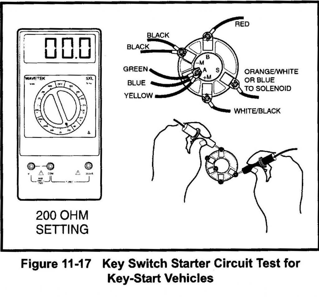
While the majority of the ignition switch terminals may not be original, the numbering for each may not match the diagram. Check the integrity of the wires to ensure that they are plugged into the ignition switch in the correct way. This can be done using a cheap multimeter. Once you are satisfied that all wires are in good order, you can attach the new connector. The wiring loom used in the ignition system switch supplied by the manufacturer differs.
First, understand the differences between the ACC and secondary outputs. The ACC and IGN terminals are the default connections on the ignition switch. the START and IGN terminals are the principal connections to the stereo and radio. The ignition switch is responsible to turn the car’s engines on and off. The terminals of older cars’ ignition switches are labeled with “ACC” and ST (for individual magneto wires).
Terminals for coil
The language used to decide the kind and model of the ignition coil is the most important thing. You’ll see a number of connections and terminals on an ignition wiring schematic that include two primary and two secondary. Each coil has a specific operating voltage. To determine which type of coil you have first, you need to check the voltage at S1, which is the primary terminal. To determine whether it’s a Type A, C, or B coil you should also test the resistance on S1’s.
The chassis’ negative end should be connected to connect the coil’s low-tension side. This is what is known as the ground for the wiring for ignition. The high-tension side delivers positive directly to the spark plugs. The coil’s aluminum body needs to be connected to the chassis for suppression, but it isn’t electrically required. The wiring diagram will depict the connection between positive and negative coils. Sometimes, an inspection at an auto part store can identify a problem with the ignition wire.
The black-and-white-striped wire from the harness goes to the negative terminal. The terminal that is negative is served by the black trace connected to the white wire. The black wire is connected to the contactbreaker. If you’re not sure about the connection between the twowires, use an old paper clip to take them from the plug housing. Make sure that the connectors do not bend.
Accessory Terminals
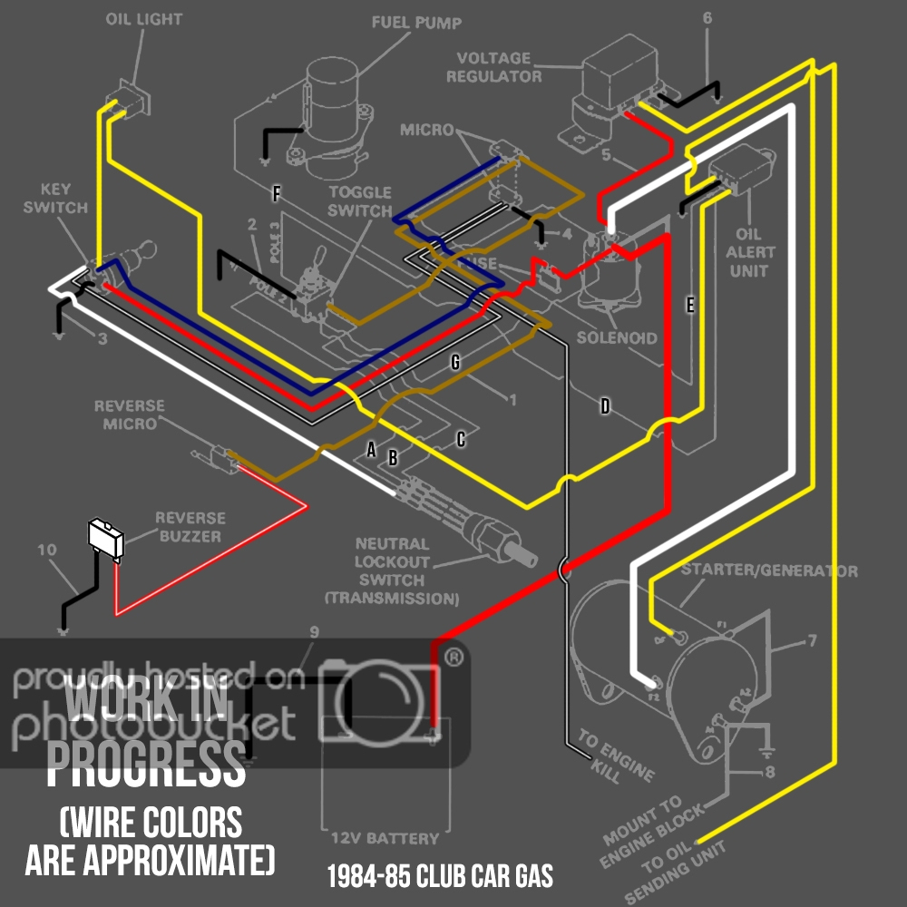
The wiring diagrams for the ignition show the different wires used to are used to power various components of the car. There are usually four different colors of terminals connected to each part. Red refers to accessories, yellow to the battery and green the starter solenoid. The “IGN terminal” is used to provide power to the wipers and other operating functions. The diagram shows how to connect ACC or ST terminals and the rest.
The battery is attached to the terminal whose name is BAT. The electrical system is not able to start without the battery. Additionally, the switch won’t begin to turn on. If you’re not sure the exact location where the battery in your car is situated, look at the wiring diagram of your car to determine how to locate it. The ignition switch is connected to the car’s battery. The BAT connector is connected to your battery.
Certain ignition switches provide the option of an “accessory position” that lets users adjust their outputs independently of the ignition. Sometimes, users want to utilize an additional output that is independent of the ignition. To allow the auxiliary output to be used, plug in the connector with the same color as the ignition. Then connect it with the ACC end of the switch. This feature of convenience is fantastic however there’s a differentiator. Most ignition switches are set to have an ACC position when the vehicle is in the ACC position, while they’re in the START position when the car is in the IGN position.
Gallery of Gas Club Car Ignition Switch Wiring Diagram

Gallery of Gas Club Car Ignition Switch Wiring Diagram


