Generator Ignition Coil Wiring Diagram – Let’s first examine the various terminals on the ignition switch. These are the terminals for the Ignition, Coil, or Accessory. Once we know the purpose of each type of terminal, we are able to determine the components of the ignition wiring. In addition, we will discuss the function of the Ignition switch and Coil. We’ll then turn our attention to the accessory terminals.
The terminals of the ignition switch
Three switches can be found on an ignition switch. Each of these switches transmits the battery’s current to several different locations. The first switch provides power to the choke when it is pushed. The second is the ignition switch’s ON/OFF position. Every manufacturer has its own color-coding system, which we’ll discuss in a subsequent article. OMC utilizes this method. Connectors can be connected to the ignition switch in order to add a digital tachometer.
Although some ignition switch terminals might not be original, the numbers of the terminals may not be in line with the diagram. To ensure that the wires are connected to the switch, it is recommended to check their continuity. This can be checked with a simple multimeter. Once you are satisfied that the wires are in good order, you can attach the new connector. If your car is equipped with an original ignition switch supplied by the factory (or a wiring loom), the wiring loom may differ from the one in your vehicle.
It is important to know the differences between the ACC and auxiliary outputs. The ACC, IGN and START terminals are the primary connections to the ignition switch. They also serve as the primary connections to the radio and stereo. The ignition switch is the one that turns the car’s engine on and off. In older vehicles, the ignition switch terminals are identified with the letters “ACC” and “ST” (for distinct magnetic wires).
Terminals for coil
Understanding the terms is the initial step in finding out what kind of ignition coil you have. The diagram of the basic ignition wiring illustrates a variety of connections and terminals. There are two primary and one secondary. The voltage that operates on each coil is different. It is important to first test the voltage at the S1 (primary terminal). To determine if it is an A, C, or B coil, you should also test S1’s resistance.
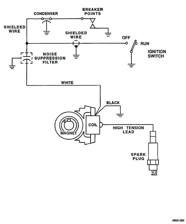
The low-tension coil side must be connected at the chassis’s less. It is also the ground in the diagram of ignition wiring. The high-tension supply delivers the spark plugs with positive electricity directly. It is essential for suppression purposes that the coil’s metallic body be connected to the chassis, however it isn’t essential. The ignition wiring diagram will also demonstrate the connection of the negative and positive coil terminals. In some cases, a scan at your local auto parts store will help identify defective ignition coils.
The black-and-white-striped wire from the harness goes to the negative terminal. The positive terminal receives the white wire and a trace in black. The black wire is connected to the contact breaker. To verify the connections, use a paperclip or a pencil to pull them out of the housing for the plug. Make sure that the connectors don’t bend.
Accessory terminals
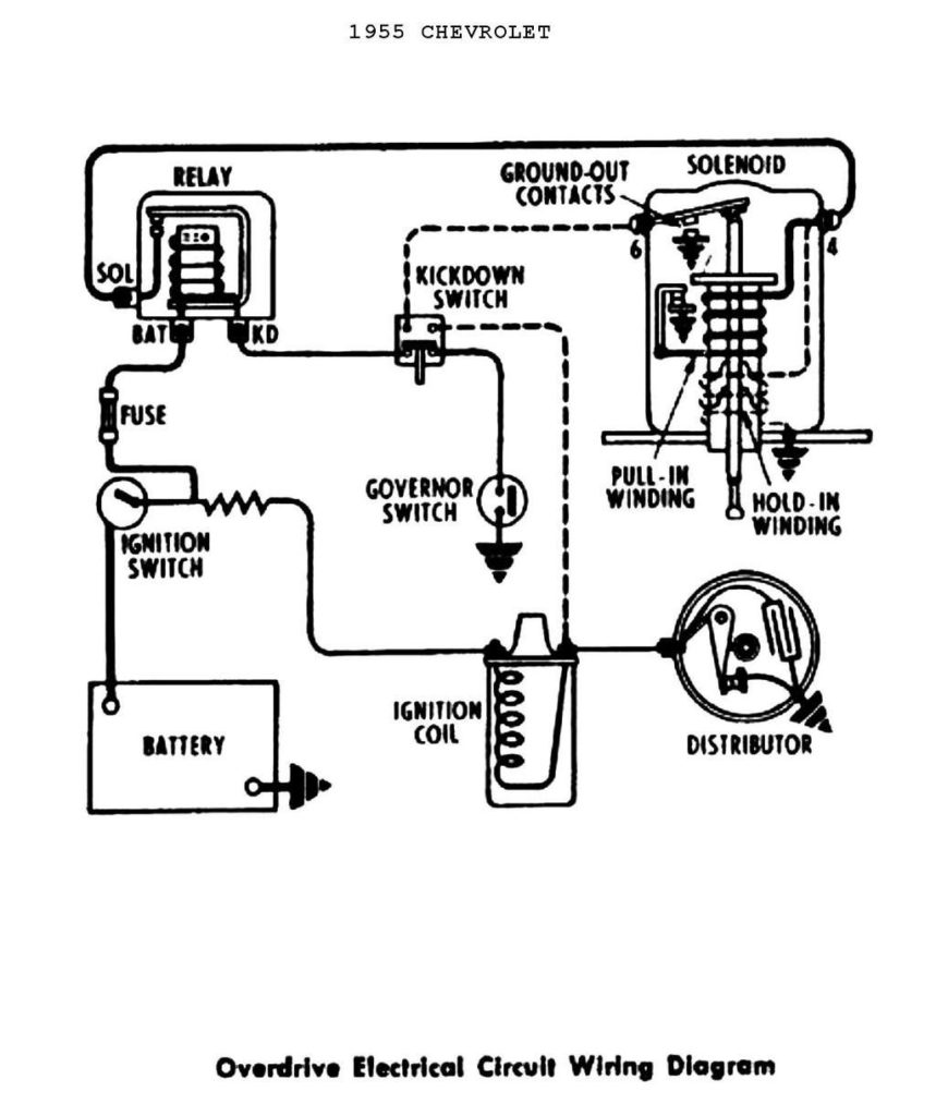
Diagrams of ignition wiring show the different wires that are utilized to power the vehicle’s various parts. Each component is equipped with four distinct color-coded connections. The accessories are colored red, the battery is yellow, and the starter solenoid is green. The “IGN terminal” is used to provide power to the wipers as well as other operating features. The below diagram shows how to connect the ACC terminal as well as the ST terminals to various components.
The terminal BAT is the connection to the battery. The electrical system won’t start if the battery isn’t connected. Additionally the switch isn’t turned on. You can view your wiring diagram to determine the location of your car’s batteries. located. The accessory terminals in your car connect to the ignition switch as well as the battery. The BAT terminal is connected to the battery.
Some ignition switches feature an additional “accessory” position, where users can manage their outputs without using the ignition. Some customers may prefer to use the auxiliary output separately from the ignition. You can utilize the additional input by connecting the connector to the ACC terminal. Although this is a fantastic option, there’s a thing to be aware of. Most ignition switches are set to operate in the ACC position when the car is in the ACC position, whereas they’re in the START position when the vehicle is in the IGN position.
Gallery of Generator Ignition Coil Wiring Diagram
Gallery of Generator Ignition Coil Wiring Diagram


