Generator Ignition Switch Wiring Diagram – Let’s begin by examining the different kinds and functions of terminals on the ignition switches. These terminals include the Ignition switch, the Coil along with the Accessory. Once we’ve established the purpose of the terminals it is possible to recognize the various parts of the ignition wiring. In addition, we will discuss the different functions of the Ignition Switch and the Coil. Following that, we will discuss the Accessory Terminals.
Terminals for ignition switch
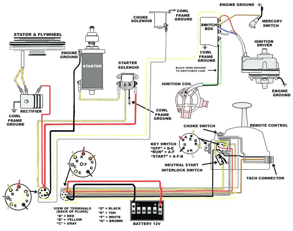
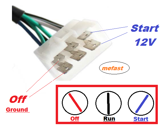
There are three different switches on the ignition switch, and they feed the battery’s voltage to various destinations. The first switch supplies power to the choke whenever it is pushed. The third is the position of the ignition switch’s ON/OFF. Different manufacturers use different color-coding methods to identify different conductors. This will be covered in another article. OMC follows the same system. A connector can be added to the ignition switch to include an electronic tachometer.
Although the majority of ignition switch terminals don’t have an original number, they might be equipped with a different number. To make sure that the wires are properly connected to the switch you must verify their continuity. This can be checked using a simple multimeter. Once you’ve verified the integrity of the wires you can then connect the connector. The wiring loom used for the ignition switch factory-supplied will be different than the one in your vehicle.
You must first understand how the ACC outputs and auxiliary outputs work in order to join them. The ACC/IGN terminals act as the default connections for the ignition switch. The START/IGN connections connect to the radio or stereo. The ignition switch regulates the engine in your car. In older vehicles the ignition switch’s terminals are marked with the initials “ACC” as well as “ST” (for individual magnet wires).
Terminals for coil
To figure out the type of ignition coil you need to know the step is to know the definition of. You will see several connections and terminals within an ignition wiring schematic which includes two primary as well as two secondary. Each coil comes with its own operating voltage. To determine the type of coil you have the first step is to test the voltage at the S1 primary terminal. S1 should also be tested for resistance in order to identify if the coil is an A, Type B, or an A coil.
The low-tension side of the coil needs to be connected to the chassis the negative. This is also the ground for an ignition wiring diagram. The high-tension supply delivers the spark plugs with positive electricity directly. The metal body of the coil needs to connect to the chassis for suppression purposes, but it is not electrically necessary. The wiring diagram for ignition will also outline how to connect the positive coil’s terminals. In some instances it is possible to find an ignition coil that is malfunctioning can be diagnosed with scanning in an auto parts store.
The black-and-white-striped wire from the harness goes to the negative terminal. The negative terminal is served by the black trace that’s attached to the white wire. The black wire is connected to the contact breaker. To check the connections between the two wires employ a paperclip to remove them out of the housing. It is also important to ensure that the terminals are not bent.
Accessory terminals
The diagrams for ignition wiring depict the wires that are used in the power supply of the vehicle. There are generally four colors of terminals connected to each part. Red is used for accessories and yellow is for the battery, while green is the solenoid for starters. The “IGN” terminal can be used to turn on the car, control the wipers, as well as other functions. The diagram demonstrates how to connect the ACC and ST terminals to the rest of the components.
The terminal BAT holds the battery. The electrical system won’t start without the battery. Furthermore the switch isn’t turned on. To locate your car’s battery examine the wiring diagram. The accessory terminals of your car are connected to the ignition switch as well as the battery. The BAT terminal is connected to the battery.
Some ignition switches have the “accessory” setting that permits users to control their outputs without having to use the ignition. Customers may want to use the auxiliary output separately from the ignition. You can use the auxiliary output by connecting the connector to an ACC terminal on your switch with the same colors. This is a great convenience feature, but there is one difference. Most ignition switches come with the ACC position when your car is in ACC mode and a START position when the switch is in IGN.
Gallery of Generator Ignition Switch Wiring Diagram
Gallery of Generator Ignition Switch Wiring Diagram


