Gm Hei Ignition Wiring Diagram – We will first look at the various kinds and functions of terminals that are found on the ignition switches. These terminals are used for the Ignition button, Coil and Accessory. Once we understand the function of each type of terminal, we are able to identify the parts of the ignition wiring. We will also cover the roles of both the Ignition Switch and Coil. After that, we’ll turn our attention to the Accessory terminals.
Ignition switch terminals
An ignition switch is composed of three different switches. These are responsible for feeding the battery’s energy to various destinations. The first switch provides the choke with power, and the third switch toggles the status of the ignition switch. Every manufacturer has its individual color-coding system that we will discuss in another article. OMC utilizes this system. The connector permits the attachment of a speedometer to the ignition switch.
Although the majority of ignition switch terminals don’t have an initial number, they could have a different one. Check the continuity of the wires to see if they are plugged into the correct ignition switch. This can be checked using an inexpensive multimeter. After you have verified the integrity of the wires you can then connect the connector. The wiring loom for an ignition switch that’s factory-supplied will be different than the one you have in your car.
For connecting the ACC outputs to the auxiliary outputs of your vehicle, you have first know the way these two connections function. The ACC and IGN terminals are the default connections on your ignition switch. the START and IGN terminals are the principal connections for radio and stereo. The ignition switch is the one that turns the car’s engine to and off. Older vehicles have ignition switch terminals marked “ACC” or “ST” (for individual magnetowires).
Terminals for coil
Understanding the terminology is the first step to knowing what type of ignition coil you own. In a basic ignition wiring diagram, you will see a number of different terminals and connections, including two primary and two secondary. It is essential to identify the kind of coil you have by testing the voltage at the primary terminal S1. S1 should also be checked for resistance to determine if the coil is an A, Type B, or an A coil.
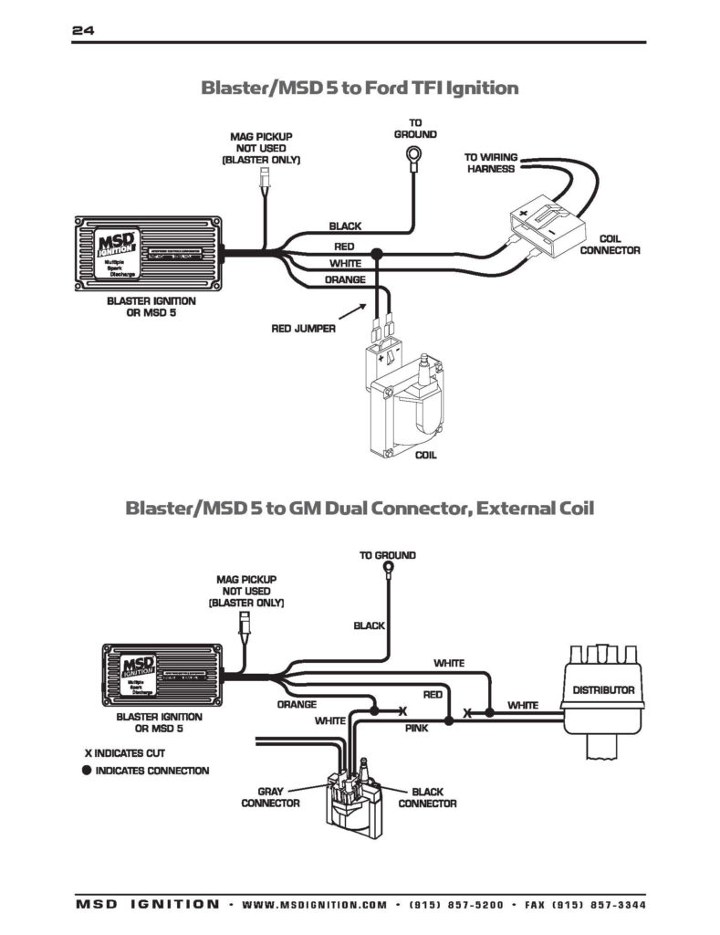
The coil’s low-tension end must be connected with the chassis positive. This is what’s called the ground on the wiring diagram for ignition. The high-tension supply delivers positive directly to spark plugs. It is necessary for the purpose of suppression that the body of the coil’s metal be connected to its chassis, but not essential. You will also see the connections of the positive and negative coil’s terminals on an diagram of the ignition wiring. There could be an ignition coil problem which can be identified by scanning it at an auto parts store.
The black-and-white-striped wire from the harness goes to the negative terminal. The other white wire has a black trace on it, and connects to the positive terminal. The black wire is connected to the contact breaker. You can take the black wire from the plug housing using a paper clip If you’re unsure of the connections. It’s also essential to make sure the terminals aren’t bent.
Accessory terminals
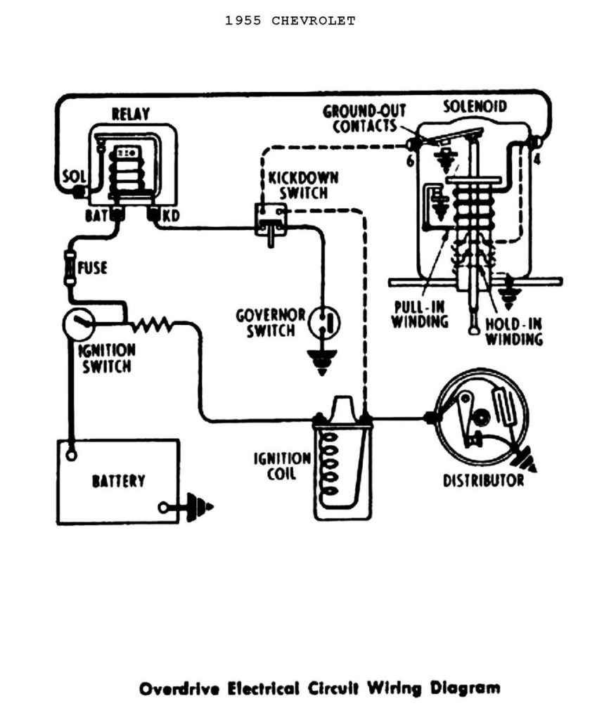
Diagrams of ignition wiring depict the wiring used to power the vehicle’s electrical supply. There are usually four terminals with color codes that are connected to the respective component. The red color is used for accessories while yellow is the battery, and green is the solenoid for starters. The “IGN” terminal can be used to start the car , and also to operate the wipers as well as other operational functions. This diagram shows how you can connect ACC and ST terminals with the rest of components.
The terminal referred to as BAT is where the battery is connected. The electrical system will not start when the battery isn’t connected. Additionally, the switch will not be able to turn on without the battery. If you don’t know the exact location where the battery in your car is located, you can look at the wiring diagram of your car to determine where it is. The accessory terminals in your car connect to the battery and the ignition switch. The BAT terminal is connected to the battery.
Some ignition switches are equipped with an accessory position. This allows users to connect their outputs to another location without having to turn on the ignition. Some customers might want to use the auxiliary output separately from the ignition. For the auxiliary output to be used, connect the connector to the same shade as that of the ignition. Connect it to the ACC end of the switch. Although this is a useful feature, there’s one important difference. Most ignition switches come with the ACC position when your vehicle is in the ACC mode, and a START position when you are in IGN.
Gallery of Gm Hei Ignition Wiring Diagram
Gallery of Gm Hei Ignition Wiring Diagram


