Gm Ignition Control Module Wiring Diagram – The first step is to take a look at the different types of terminals that are used in the ignition switch. These terminals include the Ignition switch, the Coil along with the Accessory. Once we know the purpose of each type of terminal, we are able to identify the various components of the ignition wiring. We’ll also discuss the functions as well as the Coil. Then, we will focus on the accessories terminals.
Terminals for ignition switches
An ignition switch has three switches. They feed the voltage of the battery to many different places. The choke is powered by the first switch. The second switch controls the ON/OFF switch of the ignition switch. Different manufacturers use different colors-coding systems to match the conductors. OMC uses this method. The adapter is attached to the ignition switch that allows for the addition of the Tachometer.
Even though some of the ignition switch terminals may not be authentic, the numbering of each one might not be in line with the diagram. Check the integrity of the wires first to ensure that they are correctly plugged in the ignition switch. This can be done with a multimeter that is inexpensive. Once you’re satisfied about the integrity of your wires, you’ll be able to install the new connector. The wiring loom used for an ignition switch that is supplied by the manufacturer will differ from the one you have in your vehicle.
In order to connect the ACC outputs to the auxiliary outputs of your car, you need to first understand how these two connections work. The ACC and IGN terminals are the default connections for the ignition switch. the START and IGN terminals are the principal connections to the stereo and radio. The ignition switch acts as the engine’s switch to turn off or on. The ignition switch terminals on older cars are identified with the initials “ACC” and “ST” (for each magneto wires).
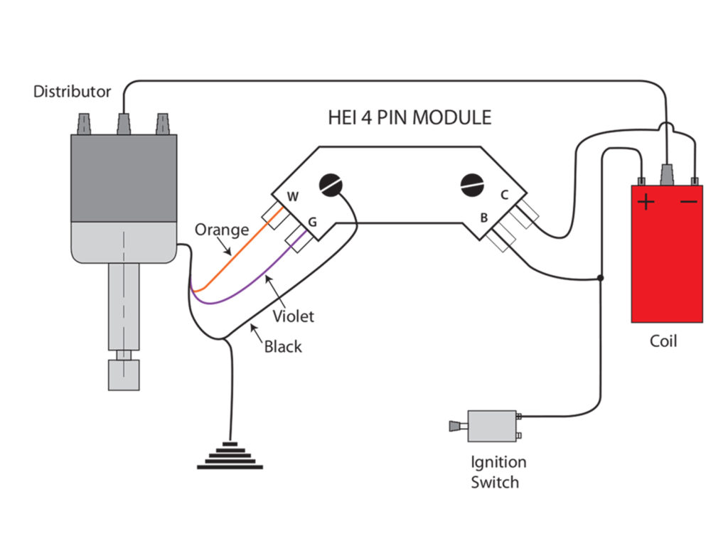
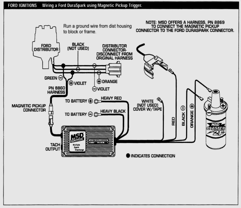
Terminals for coil
To determine the type of ignition coil you need to know the step is to learn the definition of. In a basic ignition wiring diagram there are various connections and terminals, such as two primary and two secondary. You must determine the type of coil that you are using by testing the voltage on the primary terminal S1. S1 must also be subjected to resistance testing to determine if it’s an A or B coil.
The negative end of the chassis should be connected to connect the coil’s low-tension end. This is the ground in the wiring diagram for ignition. The high-tension end provides positive direct to the sparkplugs. The coil’s aluminum body needs to be connected to the chassis for suppression however it’s not electrically required. A wiring diagram can also show the connection between the positive and negative coil terminals. In some instances it is possible to find the ignition coil is damaged and can be diagnosed with a scan at an auto parts shop.
The black-and-white-striped wire from the harness goes to the negative terminal. The other white wire is black with a trace on it, and it goes to the positive terminal. The black wire connects to the contact breaker. If you’re not certain about the connections between the twowires, use a paper clip to remove them from the plug housing. Make sure that the connectors aren’t bent.
Accessory terminals
Diagrams of ignition wiring illustrate the wires used in the vehicle’s power supply. Typically, there are four different colored terminals for each part. Red refers to accessories, yellow is the battery, and green the starter solenoid. The “IGN” terminal allows you to start the car, manage the wipers, and any other operation features. The diagram shows the connection to the ACCand ST terminals.
The terminal BAT is the connector for the battery. The electrical system won’t start when the battery isn’t connected. In addition, the switch will not start. To locate your car’s battery, check your wiring diagram. The accessory terminals of your car connect to the ignition switch as well as the battery. The BAT terminal is connected with the battery.
Certain ignition switches provide the option of an “accessory position” that allows users to alter their outputs without the ignition. Sometimes, customers wish to make use of an auxiliary output that is separate from the ignition. To allow the auxiliary output to be used, plug in the connector in the same color as that of the ignition. Then connect it with the ACC end of the switch. This convenience feature is great however there’s a differentiator. The majority of ignition switches have an ACC position when the vehicle is in ACC however they’ll be in the START position if the vehicle is in IGN.
Gallery of Gm Ignition Control Module Wiring Diagram

Gallery of Gm Ignition Control Module Wiring Diagram


