Gm Ignition Module Wiring Diagram – First, let’s take a look at the different types of terminals on the ignition switch. They are the terminals used that are used for Coil, Ignition Switch, and Accessory. After we’ve identified the terminals used then we can recognize the various parts of the Gm Ignition Module Wiring Diagram. We’ll also discuss the functions of both the Ignition Switch and the Coil. After that, we’ll turn our attention to Accessory terminals.
The terminals are for ignition switches.
The ignition switch consists of three switches. These are the ones that supply the battery’s power to various destinations. The choke is powered by the first switch. The second switch is responsible for the ON/OFF switch of the ignition switch. Different manufacturers use different color-coding methods for different conductors. This will be covered in a separate article. OMC uses this method. A tachometer adapter is installed on the ignition switch, allowing the installation of an tachometer.
While the majority of ignition switch terminals don’t carry an initial number, they could have a different number. Examine the integrity of the wires first to ensure they are correctly plugged in the ignition switch. You can check this using an inexpensive multimeter. Once you are satisfied that the wires are in good order and you are able to connect the new connector. If your car has an original ignition switch supplied by the factory (or a wiring loom) The wiring loom might differ from the one in your vehicle.
To connect the ACC outputs to the auxiliary outputs on your car, you need to first understand the way these two connections function. The ACC/IGN terminals function as the default connection on the ignition switch. The START/IGN terminals are connected to the stereo or radio. The ignition switch turns the engine of your car ON and OFF. The terminals for the ignition switch on older cars are identified with the alphabets “ACC” as well as “ST” (for each magneto wires).
Terminals for coil
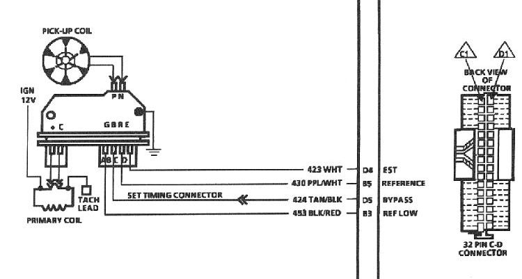
The language used to decide the model and type of the ignition coil is the first thing. The diagram of the basic ignition wiring shows a number different connections and terminals. There are two primary and secondary connections. You need to determine the kind of coil you have by testing the voltage at the primary terminal S1. S1 should also be checked for resistance to determine if it’s an A, Type B or A coil.
The chassis’ negative should be connected to connect the coil’s low-tension side. It is also the ground in the diagram of ignition wiring. The high-tension side supplies the spark plugs with positive. To prevent noise, the coil’s metal body is required to be connected to the chassis. However, it is not necessary to connect the coil electrically. The diagram of the ignition wiring will also demonstrate the connection of the positive and negative coil terminals. Sometimes, a check at an auto part store can diagnose a malfunctioning ignition wire.
The black-and-white-striped wire from the harness goes to the negative terminal. The positive terminal also receives a white wire that is black in its trace. The black wire connects to the contactbreaker. If you’re not certain about the connections between the twowires, use a paper clip to remove them from the housing of the plug. Also, make sure that the connections aren’t bent.
Accessory terminals
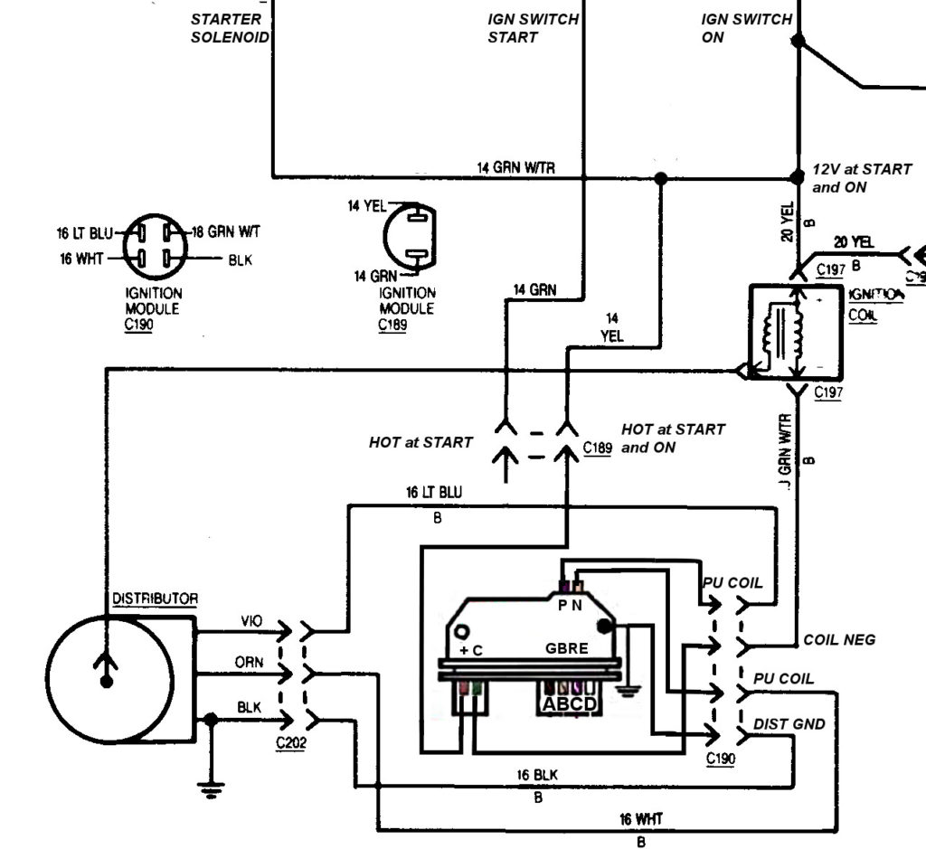
Diagrams of the ignition wiring depict the wires used to supply power to different parts of the car. There are usually four color-coded terminus for each component. Red is used for accessories and yellow is for the battery, while green is for the solenoid for starters. The “IGN” terminal is used to turn on the vehicle and control the wipers as well as other operational functions. The diagram below shows how to connect both the ACC terminal and ST terminals to the other components.
The terminal called BAT is the location where the battery is. The electrical system can’t begin without the battery. The switch also won’t be able to turn on without the battery. To find the battery in your car, check your wiring diagram. The accessory terminals of your car are connected to the ignition switch and the battery. The BAT terminal connects to the battery.
Some ignition switches feature an additional “accessory” position, in which users can control their outputs without the ignition. Sometimes, a customer wants to use an auxiliary output that is separate from the ignition. Use the additional output by connecting it to the ACC terminal on the switch that has the same color. This is a great feature, but there is one important difference. Most ignition switches come with the ACC position when your car is in ACC mode, and a START position when it is in IGN.
Gallery of Gm Ignition Module Wiring Diagram

Gallery of Gm Ignition Module Wiring Diagram


