Harley 6 Pole Ignition Switch Wiring Diagram – We’ll begin by looking at different types terminals found in an ignition switch. These terminals include the Ignition switch as well as the Coil as well as the Accessory. After we’ve established what these kinds of terminals are for then we can discover the various components of the Harley 6 Pole Ignition Switch Wiring Diagram. We’ll also discuss the roles of the Ignition switch, as well as the Coil. Then we’ll discuss the Accessory Terminals.
Terminals for the ignition switch
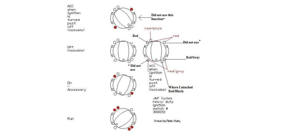
There are three switches on the ignition switch, and they transmit the battery’s current voltage to a variety of destinations. The first switch is the one that supplies the choke with power, and the third switch toggles the on/off state of the switch. Different manufacturers use their own color-coding systems for the various conductors, which is documented in another article. OMC follows the same system. Connectors can be attached to the ignition switch to include the digital tachometer.
While most ignition switch terminals aren’t original, the numbers for each might not be consistent with the diagram. Check the electrical continuity to determine if they’re plugged into the ignition switch in the correct way. You can do this with a simple multimeter. After you’re satisfied with the connection, you can place the new connector. If you’re using an ignition switch that is supplied by the manufacturer the wiring loom may be different from that used in your vehicle.
The first step is to understand the distinctions between the ACC and secondary outputs. The ACC terminals as well as the IGN terminals serve as the primary connections to your ignition switch. The START and IGN connections are the main connections for stereo and radio. The ignition switch regulates the engine in your car. Older cars are identified with the alphabets “ACC”, “ST”, (for individual magneto cables) at the ignition switch terminals.
Terminals for coil
Understanding the terms is the first step to finding out what kind of ignition coil you’ve got. An ignition wiring diagram will reveal a variety of terminals and connections, comprising two primary and two secondaries. The coils are equipped with a particular operating voltage. The first step to determine which one you’re using is to test the voltage at S1, the primary terminal. S1 must be checked for resistance to determine if the coil belongs to Type A, B, or C.
The lower-tension side of the coil should be connected to the chassis”negative. This is exactly what you can see on the wiring diagram. The high-tension part connects the spark plugs to a positive. For suppression purposes the coil’s body metal must be connected with the chassis. It is not required for electrical use. The diagram of the ignition wiring will also show you the connections between the positive and negative coil terminals. There could be an ignition coil problem which can be identified by looking it up at the auto parts shop.
The black-and-white-striped wire from the harness goes to the negative terminal. The positive terminal receives the other white wire, which has a trace in black. The black wire connects to the contact breaker. You can examine the connections with a paperclip to remove the wires from the housing. It is also important to make sure that the connections aren’t bent.
Accessory terminals
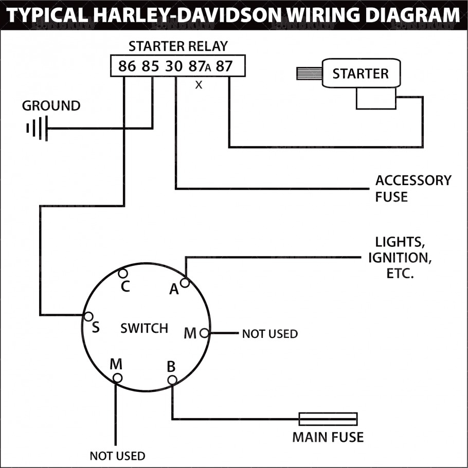
Diagrams of the ignition wiring show the wires that power various parts of the vehicle. There are generally four colored terminals that correspond to each component. For accessories, red stands for starter solenoid, blue for battery, and blue for accessories. The “IGN terminal” is used to provide power to the wipers as well as other operating functions. This diagram shows how you can connect ACC and ST terminals to the rest of components.
The battery is attached to the terminal named BAT. The battery is vital for the electrical system to get started. In addition, the switch will not begin to turn on. It is possible to view the wiring diagram of your car to see where the batteries of your car are located. The ignition switch and the battery are connected through the accessory terminals. The BAT Terminal is connected to the battery.
Certain ignition switches come with an accessory position where users can modify their outputs and control them without having to turn on the ignition. Some customers prefer to use an auxiliary output independent of the ignition. The auxiliary output could be used to connect the connector with the same colors as your ignition and connecting it to the ACC terminal of the switch. This option is useful however, it does have one major differentiator. Most ignition switches come with the ACC position when your vehicle is in the ACC mode, and a START position when you are in IGN.
Gallery of Harley 6 Pole Ignition Switch Wiring Diagram
Gallery of Harley 6 Pole Ignition Switch Wiring Diagram


