Honda Foreman Ignition Switch Wiring Diagram – We will first look at the various types and purposes of the terminals on the ignition switches. These are the terminals that connect the Ignition, Coil, or Accessory. Once we have identified what these terminals do, we will determine the various components in the ignition wiring. In addition, we will discuss the roles of the Ignition switch and Coil. Next, we’ll discuss the roles of the ignition switch and Coil.
Terminals for the ignition switch
There are three separate switches on the ignition switch, and they feed the battery’s voltage to various places. The first one supplies the choke with power when it is pushed. The second is the position of the ignition switch’s ON/OFF. Different manufacturers have various color codes for the various conductors. This is described in another article. OMC follows this system. This connector allows the connection of a speedometer to the ignition switch.
While many ignition switch terminals could not be authentic, the numbering of each may not be in line with the diagram. To make sure that the wires are properly connected to the switch, it is recommended to check their continuity. A multimeter is a great tool to test the continuity. Once you are satisfied with the integrity of the wires install the new connector. If your car is equipped with an original factory-supplied ignition switch (or an electrical loom) The wiring loom may differ from that in your car.
Before you can connect the ACC outputs to your car’s auxiliary outputs It is essential to be familiar with the fundamentals of these connections. The ACC and IGN connectors are the standard connections for your ignition switch. While the START, IGN, and ACC terminals are the main connections to the radio or stereo, the START/IGN connections are the most important ones. The ignition switch regulates the engine in your car. The terminals for the ignition switch on older cars are identified with the alphabets “ACC” as well as “ST” (for individual magneto wires).
Terminals for coil
Understanding the terminology used is the first step in determining the type of ignition coil. A simple diagram of the wiring will display a range of connections and terminals, comprising two primary and two secondary. Each coil is operating at a certain voltage. The first step to determine which kind of coil you’re dealing with is to test the voltage on S1, or the primary terminal. S1 must also be inspected for resistance to determine whether it’s an A, Type B or A coil.
The coil’s low-tension component is to be connected to the chassis’ positive. This is the ground of the ignition wiring. The high tension part supplies positive power directly to the spark plugs. To prevent noise the body of the coil is required to be connected to the chassis. It is not required to connect electrically. The wiring diagram for ignition will also outline how to connect the positive coil’s terminals. Sometimes, a damaged ignition coil can be identified with a scan at an auto repair shop.
The black-and-white-striped wire from the harness goes to the negative terminal. Positive terminal receives a white wire that has a black trace. The contact breaker is linked to the black wire. If you’re unsure of the connections of the twowires, use the clip of a paperclip to remove them from the housing of the plug. It is also important to make sure that the connections aren’t bent.
Accessory terminals
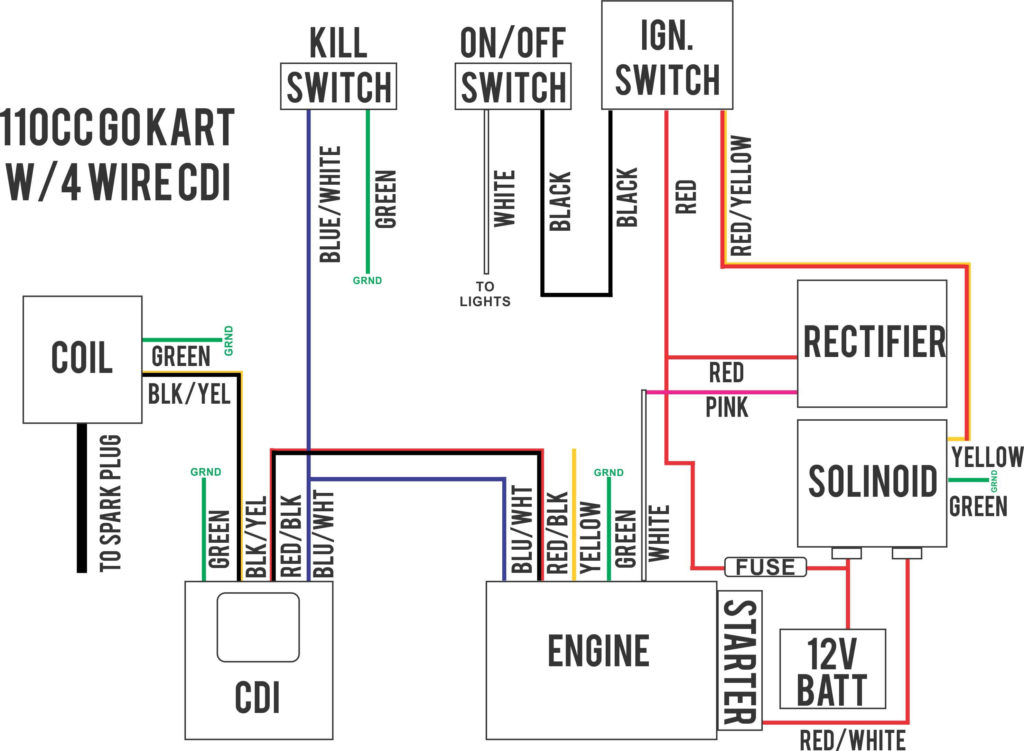
Diagrams of the ignition wiring depict the wiring used to provide power to various components of the vehicle. Typically there are four distinct colors-coded terminals that are used for each component. The red color is used for accessories while yellow is the battery, and green is the solenoid for starters. The “IGN” terminal can be used to start the car, control the wipers and other functions. The diagram shows the connection to the ACC- and ST terminals.
The terminal BAT is the connection to the battery. The electrical system is not able to start without the battery. Additionally, the switch will not turn on without the battery. You can refer to your wiring diagram if uncertain about where the car’s batteries are. The ignition switch as well as the battery are connected via accessory terminals. The BAT Terminal is connected to the Battery.
Certain ignition switches come with the “accessory” setting that allows users to control their outputs , without having to use the ignition. Sometimes, customers would like the output of the auxiliary to be used separately from the ignition. The auxiliary output can be utilized by wiring the connector with the same colors as the ignition and connecting it to the ACC terminal of the switch. Although this is a useful feature, there is one important difference. Many ignition switches have an ACC position when the car is in ACC mode and a START position when you are in IGN.
Gallery of Honda Foreman Ignition Switch Wiring Diagram
Gallery of Honda Foreman Ignition Switch Wiring Diagram


