Honda Gx620 Ignition Switch Wiring Diagram – Let’s begin by examining the different types and purposes of the terminals on the ignition switches. These are terminals that are used for Coil, Ignition Switch, and Accessory. Once we know which terminals are used and which ones are not, we can identify the different components of the Honda Gx620 Ignition Switch Wiring Diagram. We’ll also go over the function of the Ignition switch and Coil. Following that, we will discuss the Accessory Terminals.
Terminals for ignition switches
The ignition switch has three switches. They transmit the battery’s voltage to many different places. The choke is powered by the first switch. The second switch controls the ON/OFF switch of the ignition switch. Different manufacturers have different colors-coding systems to match the conductors. OMC utilizes this method. Connectors can be attached to the ignition switch to add an electronic tachometer.
Although the majority of ignition switch terminals aren’t authentic, the numbering of each may not match the diagram. The first step is to check the continuity of each wire to make sure they’re properly connected to the ignition switches. A multimeter is an excellent tool to check the continuity. When you’re satisfied with the integrity of the wires, then you’ll be able install the new connector. If your car has an original ignition switch supplied by the factory (or a wiring loom) The wiring loom might differ from that in the car.
The first step is to understand the distinctions between ACC and auxiliary outputs. The ACC and IGN terminals are the default connections on your ignition switch, and the START and IGN terminals are the primary connections to the stereo and radio. The ignition switch is responsible to turn the engine of your car on and off. The terminals on older cars ignition switches are marked by “ACC” and ST (for individual magneto wires).
Terminals for coil
To identify the kind of ignition coil you need to know the step is to understand the terms. A basic diagram of the wiring will show you a number of connections and terminals. You must determine the type of coil you are using by testing the voltage at the primary terminal, called S1. You should also examine S1 for resistance in order to determine whether it is a Type A, B, or C coil.
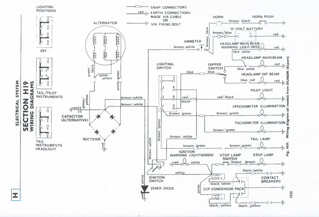
The low-tension side of the coil should be connected to the chassis’ negative. This is what’s called the ground on the wiring diagram for ignition. The high-tension part supplies the spark plugs with positive. It is necessary for suppression purposes that the coil’s metallic body be connected to its chassis but not essential. It is also possible to see the connections between the positive and the negative coil’s terminals on an ignition wiring diagram. You may find an issue with the ignition coil which can be identified by scanning it at the auto parts shop.
The black-and-white-striped wire from the harness goes to the negative terminal. The white wire has a black color and goes to the negative terminal. The black wire connects to the contact breaker. To verify the connection, use a paperclip or a pencil to pull them out of the housing for the plug. Be sure to ensure that the terminals have not been bent.
Accessory terminals
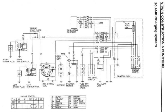
Ignition wiring diagrams show the various wires utilized to power the vehicle’s various components. There are typically four terminals with color codes that are connected to each component. The red color is for accessories, yellow is the battery, and green for the starter solenoid. The “IGN terminal” is used to run the wipers, along with other operational functions. The diagram below shows how to connect the ACC terminal as well as the ST terminals to the other components.
The terminal BAT connects the battery to the charger. Without the battery the electrical system can not get started. In addition, the switch will not begin to turn on. To locate your car’s battery look over your wiring diagram. The ignition switch is connected to the battery of your car. The BAT terminal is connected to the battery.
Some ignition switches are equipped with an additional position. This allows users to connect their outputs to another location without the ignition. Sometimes, users want to make use of an additional output that is independent of the ignition. To allow the auxiliary output to be used, wire the connector in the same shade as the ignition. Connect it to the ACC end of the switch. Although this is a useful feature, there’s one crucial distinction. Most ignition switches come with an ACC position when your vehicle is in ACC mode and a START mode when you are in IGN.
Gallery of Honda Gx620 Ignition Switch Wiring Diagram

Gallery of Honda Gx620 Ignition Switch Wiring Diagram


