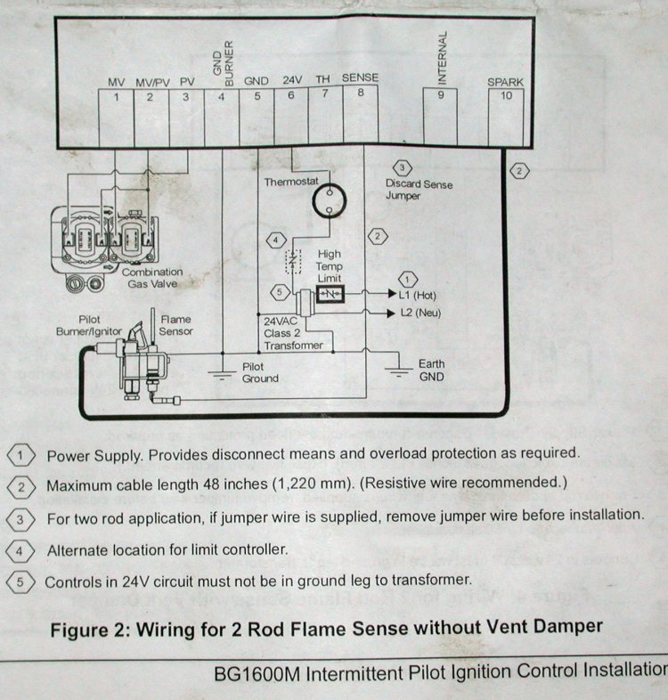
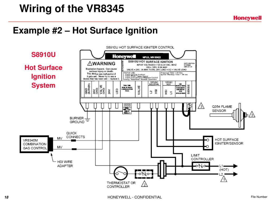
Honeywell Ignition Module Wiring Diagram – First, let’s look at the different terminals that are used in the ignition switch. These are the terminals that connect the Ignition, Coil, or Accessory. Once we understand the function of each terminal, we can then determine the components of the ignition wiring. Then, we will discuss what functions are available for the Ignition switch and the Coil. Then, we will focus on the accessories terminals.
Terminals for ignition switch
Three switches are located on an ignition switch. Each of the three switches transmits the battery’s current to several different places. The first switch is used to drive the choke by pushing it. Then, the third switch is used to control the ON/OFF setting. Different manufacturers have different color-coding systems for different conductors. This will be covered in a separate article. OMC utilizes this system. Connectors can be connected to the ignition switch in order to include an electronic tachometer.
Although the majority of ignition switch terminals don’t have an original number, they might have a different one. Check the continuity of the wires to see if they are connected to the ignition switch in the correct way. A cheap multimeter can assist you in this. Once you’re satisfied about the continuity of your wires, you’ll be able to connect the new connector. If you’re using a factory-supplied ignition switch the wiring loom may be different from that you have in your car.
Understanding how the ACC outputs connect to the auxiliary outputs in your car is essential. The ACC, IGN and START terminals are the primary connections to the ignition switch. They also function as the primary connections to your radio and stereo. The ignition switch is responsible to turn the engine of your car on and off. Older vehicles are identified with the alphabets “ACC”, “ST”, (for individual magneto cables) at their ignition switch terminals.
Terminals for coil
The language used to decide the kind and model of an ignition coil is the most important thing. An understanding of the basic wiring diagram for ignition will provide you with a range of connections and terminals. Each coil comes with its own operating voltage. To determine the type of coil you own first, you need to test the voltage at S1, which is the primary terminal. It is also recommended to test S1 for resistance in order to determine whether it is an A, B, or C coil.
The negative end of the chassis should be connected to to the coil’s lower-tension end. It is also the ground for the diagram of ignition wiring. The high-tension part connects the spark plugs to a positive. The coil’s aluminum body needs to be linked to the chassis to prevent it from being smothered however it’s not electrically required. The wiring diagram of the ignition will explain how to connect the terminals of the positive or negative coils. Sometimes, an inspection at an auto parts shop can diagnose a malfunctioning ignition wire.
The black-and-white-striped wire from the harness goes to the negative terminal. The terminal for the negative is served by the black trace attached to the white wire. The black wire is connected to the contact breaker. To test the wires’ connections, use a paperclip to remove them off the housing. It’s also essential to make sure that the terminals do not bend.
Accessory terminals
Diagrams of ignition wiring show the wires that are used in the power supply of the vehicle. Each part has four distinct colored connections. Red is used for accessories, yellow is for the battery, while green is for the starter solenoid. The “IGN terminal” is used to power the wipers and other operating features. The diagram shows how you can connect the ACC and ST terminals to the other components.
The battery is attached to the terminal whose name is BAT. The electrical system is not able to begin without the battery. The switch also won’t turn on without the battery. You can view your wiring diagram to figure out where your car’s batteries are situated. The accessory terminals in your car connect to the ignition switch as well as the battery. The BAT connector is connected to the battery.
Certain ignition switches provide an additional “accessory position” that allows users to modify their outputs independent of the ignition. Some customers prefer to use an auxiliary output that is independent of the ignition. For the auxiliary output to be used, connect the connector to the same shade as the ignition. Connect it to the ACC end of the switch. While this is a convenient feature, there’s one important difference. Most ignition switches come with the ACC position when your vehicle is in the ACC mode and a START position when you are in IGN.
Gallery of Honeywell Ignition Module Wiring Diagram
Gallery of Honeywell Ignition Module Wiring Diagram


