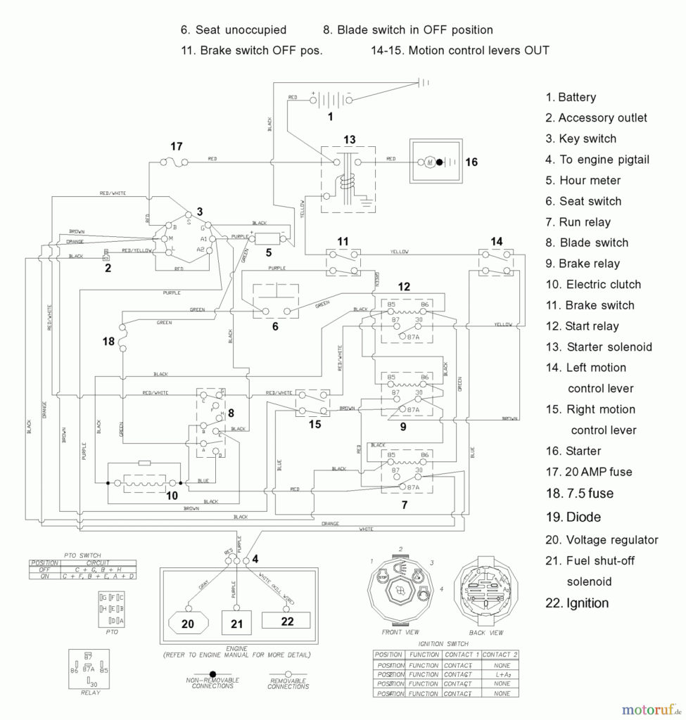
Husqvarna Riding Mower Ignition Switch Wiring Diagram – First, we will examine the various types of terminals on the ignition switch. These include terminals for Coil, Ignition Switch, and Accessory. Once we understand the function of each terminal, we can then identify the various components of the ignition wiring. We will also cover the different functions of the Ignition Switch and the Coil. The next step is to focus on the accessory terminals.
The ignition switch’s terminals
Three switches are located on an ignition switch. Each of these switches is able to feed the battery’s voltage to a variety of locations. The first switch supplies the choke with power when pushed, and the second is the ignition switch’s ON/OFF position. Different manufacturers employ various color codes for the various conductors. This is explained in a different article. OMC utilizes this method. This connector allows the connection of a speedometer to the ignition switch.
Although some ignition switch terminals might not be original, the numbering of each one might not match the diagram. Check the electrical continuity first to make sure they are correctly plugged in the ignition switch. This can be checked using a simple multimeter. Once you are satisfied that all wires are in good order, you can attach the new connector. The wiring loom used in an ignition system switch that is supplied by the manufacturer differs.
Understanding how ACC outputs are connected to the auxiliary outputs inside your car is vital. The ACC and IGN terminals are the default connections for your ignition switch. the START and IGN terminals are the primary connections for radio and stereo. The ignition switch is accountable to turn the engine of your car on and off. The terminals of older cars ignition switches are identified by “ACC” as well as ST (for the individual magneto wires).
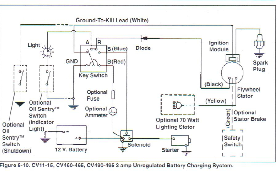
Terminals for coil
The first step in determining the kind of ignition coil is to know the terms employed. A basic ignition wiring diagram will reveal a variety of terminals and connections comprising two primary and two secondary. The coils have a specific operating voltage. The initial step to determine which one you’re using is to test the voltage at S1, the main terminal. S1 should be tested for resistance in order to determine if the coil belongs to type A, B or C.
The coil’s low-tension end must be connected with the chassis’ positive. This is also the ground in the diagram of ignition wiring. The high-tension component supplies positive direct to the spark plugs. It is required for suppression purposes that the body of the coil’s metal be connected to its chassis however, it is not necessary. It is also possible to see the connections of the positive and negative coil’s terminals on the diagram of the ignition wiring. Sometimes, a visit to an auto part store can identify a problem with the ignition wire.
The black-and-white-striped wire from the harness goes to the negative terminal. The positive terminal receives the other white wire with an black trace. The black wire connects to the contact breaker. If you’re not sure about the connection between both, you can use a paper clip to remove them from the housing of the plug. It’s also crucial to ensure that the terminals don’t bend.
Accessory Terminals
Ignition wiring diagrams show the different wires that are used to power the car’s various parts. There are typically four terminals with color codes that are connected to each component. To identify accessories, red is the starter solenoid’s color, yellow for battery, and blue is for accessory. The “IGN” terminal is used to start the car, operating the wipers, and for other functions. The diagram demonstrates how to connect the ACC and ST terminals to the other components.
The terminal called BAT is where the battery is connected. The electrical system is not able to start without the battery. Additionally, the switch will not turn on without the battery. You may refer to the wiring diagram if unsure where your car’s batteries are. The accessory terminals of your vehicle connect to the battery as well as the ignition switch. The BAT terminal is connected to the battery.
Certain ignition switches come with an accessory setting where users can adjust their outputs as well as control them without the need to use the ignition. Sometimes, customers want to use the auxiliary output separate from the ignition. In order to use the auxiliary output, wire the connector with the same colors as the ignition, and connect it to the ACC terminal on the switch. This is a useful feature, but there is one important difference. The majority of ignition switches are configured to have an ACC status when the car’s at either the ACC or START position.
Gallery of Husqvarna Riding Mower Ignition Switch Wiring Diagram
Gallery of Husqvarna Riding Mower Ignition Switch Wiring Diagram


