Ignition Coil And Distributor Wiring Diagram – First, let’s examine the various terminals used on the ignition switch. They are terminals for Coil, Ignition Switch, and Accessory. When we have a clear understanding of the purpose of each terminal, we can then identify the parts of the ignition wiring. We will also discuss the functions for the Ignition switch, as well as the Coil. Then, we’ll focus on the accessory terminals.
The terminals of the ignition switch
An ignition switch has three switches. They transmit the battery’s voltage to different places. The ON/OFF setting of the ignition switch is controlled by the second switch, which provides power to the choke whenever it is pushed. Different manufacturers use different color-coding methods to identify different conductors. This will be covered in another article. OMC follows this procedure. A tachometer adapter is installed on the ignition switch to allow the addition of the tachometer.
While the majority of the ignition switch terminals aren’t original, the numbers for each might not be consistent with the diagram. It is important to first verify the electrical continuity to determine if they’re plugged into the ignition switch in the correct way. You can do this with a simple multimeter. After you’re satisfied with the integrity of the wires, it is time to install the new connector. If you have an ignition switch supplied by the manufacturer the wiring loom will be distinct from the one that is used in your vehicle.
Understanding how the ACC outputs are connected to the other outputs in your car is vital. The ACC terminals and IGN terminals function as the standard connections for the ignition switch. The START and IGN connections are the most important connections for radio and stereo. The ignition switch switches the car’s engine on and off. In older vehicles, the ignition switch terminals are identified with the alphabets “ACC” as well as “ST” (for individual magnet wires).
Terminals for coil
Understanding the terminology is the first step towards finding out what kind of ignition coil you own. You will see several connections and terminals in a basic ignition wiring schematic that include two primary as well as two secondary. The voltage that operates on each coil is different. This is why it is important to first test the voltage at the S1 (primary terminal). It is also recommended to test S1 for resistance in order to identify if it’s a Type A, B, or C coil.
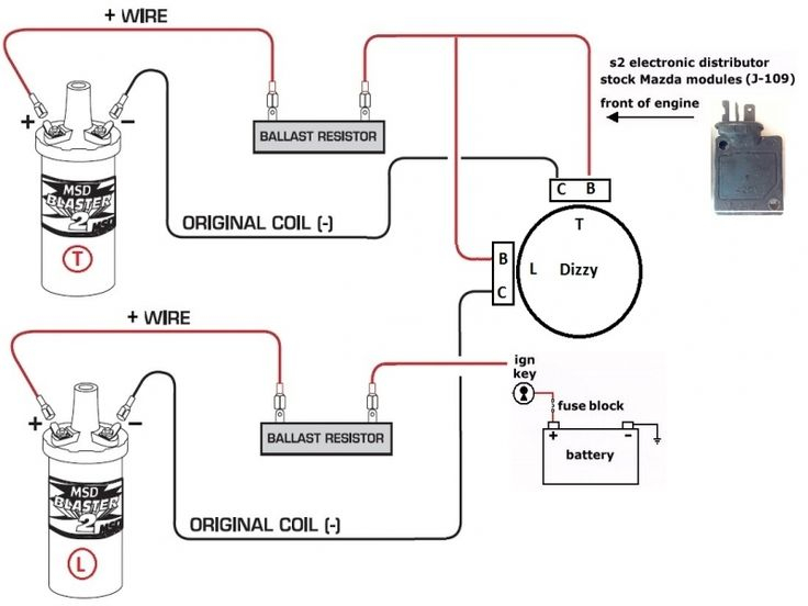
The low-tension side of the coil should be connected to the chassis”negative. This is what you see on the diagram of wiring. The high-tension supply provides positive directly to spark plugs. It is required for suppression purposes that the coil’s metallic body be connected to its chassis, but not essential. The wiring diagram will also show the connection between the positive and negative coils. Sometimes, a damaged ignition coil can be identified with a scan at an auto parts shop.
The black-and-white-striped wire from the harness goes to the negative terminal. The white wire is black and goes to the negative terminal. The contact breaker is linked to the black wire. It is possible to remove the black wire from the housing of the plug by using a paperclip If you’re unsure of the connections. Be sure the terminals aren’t bent.
Accessory terminals
The wiring diagrams of the ignition illustrate the various wires that provide power to the various parts of the car. There are usually four different colors of terminals connected to each part. Red is for accessories while yellow is the battery, and green is for the solenoid for starters. The “IGN” terminal allows you to start the car, control the wipers, and any other operation features. The diagram shows how you can connect the ACC and ST terminals to the rest of the components.
The terminal BAT connects the battery to the charger. The electrical system won’t start if the battery isn’t connected. A dead battery could make the switch stop turning on. You can refer to your wiring diagram if unsure where your car’s batteries are. The accessory terminals of your car are connected to the battery and ignition button. The BAT terminal connects to the battery.
Some ignition switches include an accessory position where users can modify their outputs as well as control them without the need to use the ignition. Sometimes, customers may wish to utilize the auxiliary input independently of the ignition. In order to use the auxiliary output, connect the connector using the same colors as the ignition and connect it to the ACC terminal on the switch. This convenience feature is great, but there is one differentiator. The majority of ignition switches are designed to have an ACC status when the car is at the ACC or START positions.
Gallery of Ignition Coil And Distributor Wiring Diagram
Gallery of Ignition Coil And Distributor Wiring Diagram


