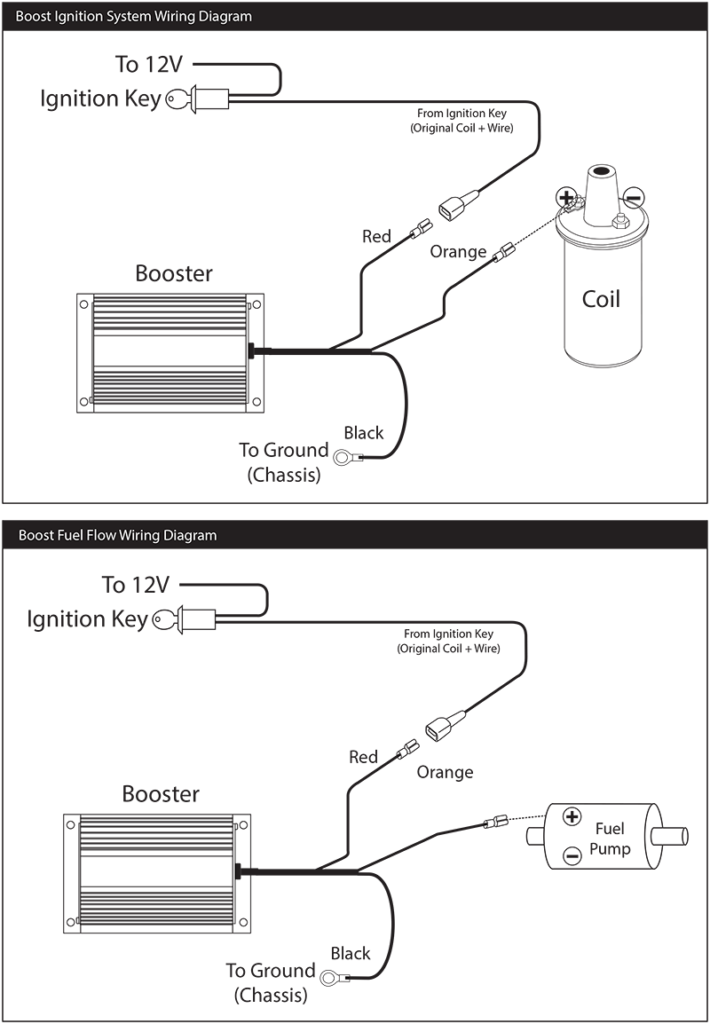
Ignition Coil Booster Wiring Diagram – First, we will take a look at the different kinds of terminals that are used on the ignition switch. These terminals comprise the Ignition switch and Coil as well as the Accessory. Once we have identified what these terminals are, we will determine the various components in the ignition wiring. We’ll also discuss the functions as well as the Coil. Then, we’ll turn our attention to Accessory terminals.
Terminals for ignition switches
An ignition switch has three switches. They supply the battery’s voltage to different places. The ON/OFF position of the switch that controls the ignition is managed by the second switch, which supplies power to the choke whenever it is pushed. Different manufacturers have various color codes for the different conductors. This is discussed in a different article. OMC follows this approach. The adapter is attached to the ignition switch, allowing the installation of a tachometer.
While most ignition switch terminals aren’t original, the numbering for each one may not be in line with the diagram. Check the continuity of the wires first to make sure they are correctly plugged in the ignition switch. This can be done with a multimeter that is inexpensive. After you’re sure that all wires are running in good harmony, you can attach the new connector. If your vehicle has an original ignition switch supplied by the factory (or a wiring loom) the wiring loom will differ from that in your vehicle.
Before you can connect the ACC outputs to your car’s auxiliary outputs, it is important to be familiar with the fundamentals of these connections. The ACC/IGN terminals function as the default connections on the ignition switch. The START/IGN connections connect to the radio or stereo. The ignition switch regulates the engine in your car. The terminals of older vehicles ignition switches are marked by “ACC” as well as ST (for individual magneto wires).
Terminals for coil
The first step to determine the kind of ignition coil is to understand the terminology that is used. In a typical ignition wiring diagram, you will see various connections and terminals, such as two primary and two secondary. The coils have a specific operating voltage. The first step in determining which type you’ve got is to check the voltage of S1 the main terminal. S1 must also go through resistance testing to determine whether it is a Type A or B coil.
The low-tension coil side must be connected to the chassis’s less. This is what’s called the ground on the ignition wiring diagram. The high-tension part connects the spark plugs to a positive. For suppression purposes, the coil’s body metal is required to be connected to the chassis. It’s not necessary for electrical use. It is also possible to see the connections of the positive and negative coil’s terminals on the ignition wiring diagram. In certain instances, a scan at your local auto parts store will be able to diagnose the malfunctioning ignition coils.
The black-and-white-striped wire from the harness goes to the negative terminal. The white wire is black-colored and goes to the terminal opposite. The contact breaker is linked to the black wire. If you’re not sure about the connections between the twowires, use the clip of a paperclip to remove them from the plug housing. It’s also crucial to ensure that the terminals don’t bend.
Accessory terminals
The diagrams for ignition wiring show the wires that are used in the power supply of the vehicle. Each part has four distinct colored connections. The accessories are red while the battery is yellow, the starter solenoid green. The “IGN” terminal can be used to start the car and operate the wipers as well as other operational functions. The diagram shows the connection to the ACCas well as ST terminals.
The battery is connected to the terminal called BAT. The electrical system can’t be started without the battery. A dead battery could cause the switch to not come on. The wiring diagram will show the location of your car’s battery. Your car’s accessory terminals are connected to the ignition switch, as well as the battery. The BAT terminal is connected to the battery.
Certain ignition switches have an accessory position where users can adjust their outputs as well as control them without the need to use the ignition. Sometimes, customers may wish to use the auxiliary input separately from the ignition. You can utilize the additional input by connecting it to the ACC terminal. This is an excellent feature, but there is an important difference. The majority of ignition switches are configured to display an ACC status when the car is in the ACC or START position.
Gallery of Ignition Coil Booster Wiring Diagram
Gallery of Ignition Coil Booster Wiring Diagram


