Ignition Coil Wiring Diagram – Let’s first look at the different terminals used on the ignition switch. These terminals serve for the Ignition button, Coil and Accessory. Once we have identified what these terminals are and what they do, we can then identify the different parts in the ignition wiring. We’ll also be discussing the functions of the Ignition switch, as well as the Coil. Then, we’ll focus to the accessory terminals.
Terminals for ignition switch
Three switches are located on the ignition switch. Each of these switches is able to feed the battery’s voltage to various destinations. The first switch provides power to the choke, while the second toggles the on/off status of the ignition switch. Every manufacturer has its unique color-coding system, which we’ll discuss in a subsequent article. OMC utilizes this system. The connector permits the attachment of a speedometer to the ignition switch.
Even though the majority of ignition switch terminals do not come in original form The numbering might not be in line with the diagram. Check the continuity of the wires to ensure that they are plugged into the correct ignition switch. A multimeter is an excellent tool to check the continuity. After you have verified the integrity of the wires you can install the connector. The wiring loom of a factory-supplied ignition system switch differs.
For connecting the ACC outputs to the auxiliary outputs on your vehicle, you have to first understand the way these two connections function. The ACC terminals and IGN terminals are the primary connections to the ignition switch. The START and IGN connections are the main connections for stereo and radio. The ignition switch regulates the engine in your car. The terminals of older vehicles ignition switches are identified by “ACC” as well as ST (for specific magneto wires).
Terminals for coil
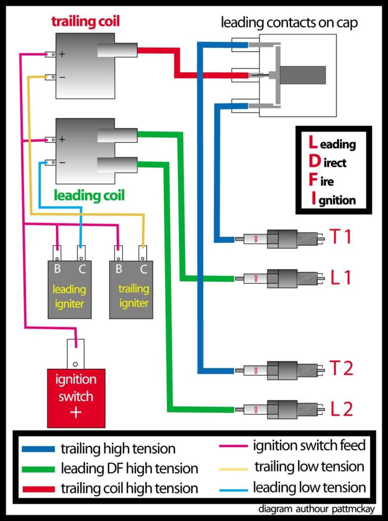
Understanding the terms is the first step to knowing what type of ignition coil you’ve got. You will see several connections and terminals in a basic ignition wiring schematic which includes two primary as well as two secondary. You need to determine the type of coil you have by testing the voltage on the primary terminal, called S1. S1 must also go through resistance testing to determine whether it is an A or B coil.
The negative of the chassis must be connected to the side of low-tension. This is also the ground for an ignition wiring diagram. The high-tension side is a positive connection to the sparkplugs. To reduce the noise the body of the coil must be connected to chassis. However, it is not necessary to connect the coil electrically. The wiring diagram of the ignition will explain how to connect the terminals of the positive or negative coils. Sometimes, a malfunctioning ignition coil can be identified with a scan in an auto parts shop.
The black-and-white-striped wire from the harness goes to the negative terminal. Positive terminal receives the white wire that is black in its trace. The black wire connects to the contactbreaker. If you’re not sure about the connection between both, you can use an old paper clip to take them from the plug housing. You should also check to see that the terminals are not bent.
Accessory terminals
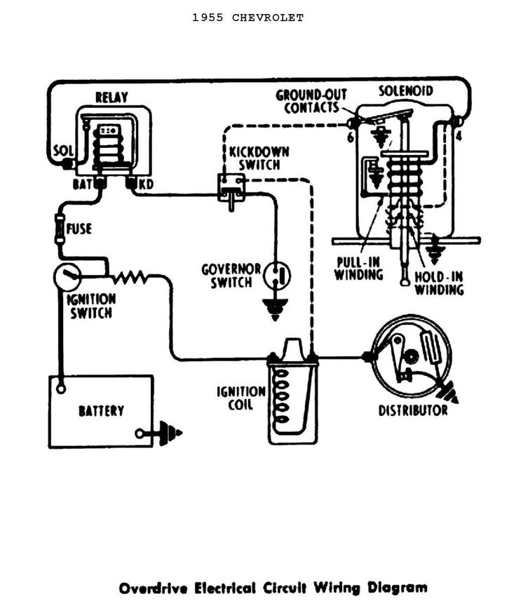
The ignition wiring diagrams illustrate the different wires that are used to power the car’s various components. In general there are four color-coded terminals for each component. The red color is used for accessories while yellow is the battery, while green is for the starter solenoid. The “IGN” terminal allows you to start the car, control the wipers, and any other features that operate. The diagram shows the connections between the ACCas well as ST terminals.
The terminal BAT is the connector for the battery. The battery is essential for the electrical system to start. Also, the switch won’t be able to turn on without the battery. You can refer to your wiring diagram if not sure where the batteries of your car are located. The accessory terminals in your car connect to the battery as well as the ignition switch. The BAT Terminal is connected to the Battery.
Certain ignition switches come with an accessory position where users can alter their outputs and manage them without the need to use the ignition. Some customers might want to utilize the auxiliary input separately from the ignition. The auxiliary output could be connected to connect the connector in the same colors as the ignition and connecting it to the ACC terminal of the switch. This feature of convenience is fantastic however, there’s one differentiator. Most ignition switches are set to operate in the ACC position when the car is in the ACC position, while they’re set to the START position when the vehicle is in the IGN position.
Gallery of Ignition Coil Wiring Diagram
Gallery of Ignition Coil Wiring Diagram


