Ignition Light Wiring Diagram – First, let’s take a look at the different types of terminals on the ignition switch. These include the terminals for the Ignition switch, Coil, and Accessory. After we’ve identified the purpose of these terminals, we will determine the various components in the ignition wiring. We’ll also be discussing the roles of the Ignition switch, and Coil. Then, we’ll turn our attention to Accessory terminals.
Terminals for ignition switches
There are three different switches on the ignition switch, and they provide the battery’s voltage to several different places. The ON/OFF state of the switch that controls the ignition is managed by the first switch, which provides the choke with power when it’s pushed. Different manufacturers use different color codes for various conductors. This is explained in a separate article. OMC follows this system. The ignition switch also includes a connector for adding a timer.
Although some ignition switch terminals might not be authentic, the numbering of the terminals may not be in line with the diagram. Check the continuity of each wire to ensure that they are properly connected to the ignition switches. This can be accomplished using a cheap multimeter. After you’re satisfied with the continuity it’s time to connect the new connector. If your vehicle is equipped with an installed ignition switch, the wiring diagram will differ.
To connect the ACC outputs to the auxiliary outputs on your vehicle, you have first know the way these two connections function. The ACC and IGN connectors are the default connections for your ignition switch. Although the START, IGN, and ACC terminals are the main connections for radios or stereo, the START/IGN connections are the primary ones. The ignition switch is responsible for turning the engine of your car on and off. On older vehicles the terminals of the ignition switch are identified with the alphabets “ACC” and “ST” (for individual magnet wires).
Terminals for coil
Understanding the terminology that is used is the initial step towards determining the kind of ignition coil you need. An understanding of the basic wiring diagram for ignition will show you a number of connections and terminals. You need to determine the type of coil that you have by testing the voltage at the primary terminal S1. S1 must also be inspected for resistance in order to identify if it’s a Type B, B, or A coil.
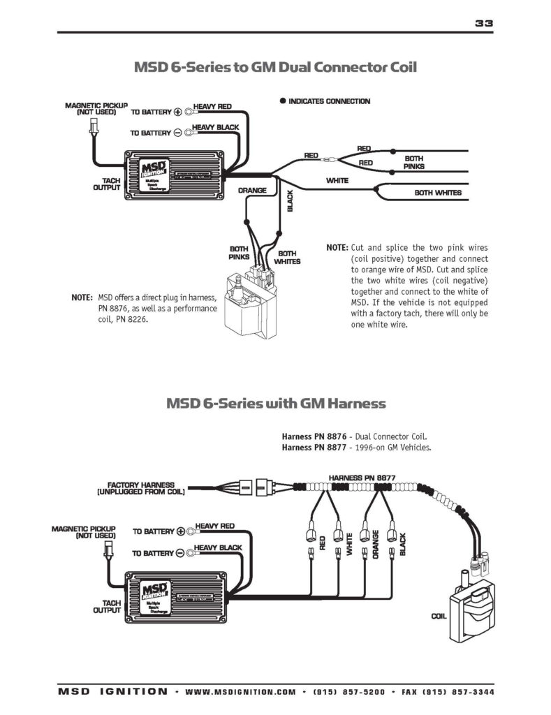
The low-tension coil side must be connected to the chassis’s plus. This is the wiring diagram you will see on the diagram of wiring. The high-tension component supplies the spark plugs with positive. For suppression purposes the body of the coil is required to be connected to the chassis. It is not necessary to electrically connect. The wiring diagram for the ignition will show you how to connect the two terminals of the negative or positive coils. In certain cases scanning the local auto parts store will help identify the malfunctioning ignition coils.
The black-and-white-striped wire from the harness goes to the negative terminal. The positive terminal also receives the second white wire, which is black in its trace. The black wire connects to the contact breaker. You can remove the black wire from the plug housing using a paper clip in case you are uncertain about the connections. It is also important to see that the terminals are not bent.
Accessory terminals
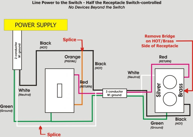
Ignition wiring diagrams depict the various wires that are used for powering the various components. There are typically four colored terminals for each component. Red stands for accessories, yellow for the battery and green for the starter solenoid. The “IGN” terminal is used to start the vehicle and control the wipers, as well as other operating features. The diagram illustrates how to connect ACC or ST terminals, and other.
The terminal BAT connects the battery to the charger. The electrical system will not start in the event that the battery isn’t connected. Additionally the switch isn’t turned on. It is possible to look up your wiring diagram to figure out the location of your car’s batteries. placed. The ignition switch and battery are connected through the accessory terminals. The BAT terminal is connected to the battery.
Certain ignition switches have an accessory position where users can adjust their outputs as well as control them without needing to use the ignition. Customers may want to use the auxiliary output in addition to the ignition. Use the secondary output by connecting it to an ACC terminal on your switch that has the same color. Although this is a fantastic feature, there’s one thing you should know. Some ignition switches are configured to be in an ACC position when the vehicle is in the ACC position. They will also be in the START position after the vehicle has been entered the IGN position.
Gallery of Ignition Light Wiring Diagram
Gallery of Ignition Light Wiring Diagram


