Ignition Module Mercedes Ignition Switch Wiring Diagram – The first step is to take a look at the different types of terminals that are used in the ignition switch. These are the terminals for the Ignition, Coil, or Accessory. After we’ve established the purpose of these terminals are then we can determine the various parts of the Ignition Module Mercedes Ignition Switch Wiring Diagram. We’ll also be discussing the roles of the Ignition switch and Coil. Next, we’ll discuss the function of the Ignition switch as well as Coil.
The terminals of the ignition switch
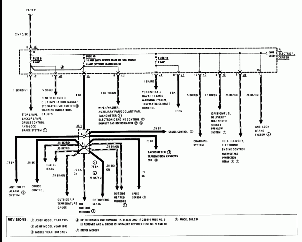
An ignition switch is made up of three switches. These are responsible for supplying the battery’s power to several places. The first switch supplies the choke with power, while the second toggles the ON/OFF status of the ignition switch. Different manufacturers have different color-coding systems for different conductors. We’ll discuss this in a different article. OMC utilizes this procedure. The ignition switch also includes an option to connect a Tachometer.
Even though the majority of ignition switch terminals do not appear in their original configuration, the numbering may not match that of the diagram. Check the continuity of the wires to determine if they’re plugged into the correct ignition switch. You can check this using an inexpensive multimeter. Once you’re satisfied with the quality of the connection, you can place the new connector. If your vehicle has an ignition switch that is installed, the wiring diagram will differ.
Before you can connect the ACC outputs to the auxiliary outputs of your car It is essential to understand the basics of these connections. The ACC and IGN terminals are the default connection on the ignition switch. the START and IGN terminals are the principal connections to the stereo and radio. The ignition switch is responsible for turning the car’s engine on and off. Older vehicles are identified with the alphabets “ACC”, “ST”, (for individual magneto cables) at their ignition switch terminals.
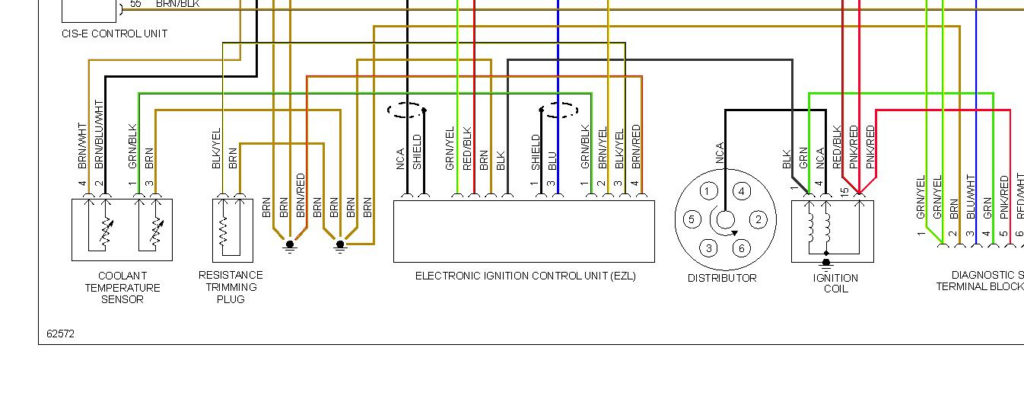
Terminals for Coil
The language used to decide the type and model of the ignition coil is the first thing. An ignition wiring diagram will reveal a variety of terminals and connections, including two primary and two secondaries. The coils have a specific operating voltage, and the first step in determining which type you’re using is to test the voltage at S1, the main terminal. To determine whether it’s a Type A, C, or B coil you must also test the resistance on S1’s.
The low-tension end of the coil must be connected to the chassis the negative. This is the ground of the wiring for ignition. The high-tension side supplies the positive power direct to the spark plugs. It is essential to suppress the metallic body of the coil is connected to the chassis, but not essential. There are also connections of the positive and negative coil terminals on the diagram of the ignition wiring. You may find an issue with the ignition coil which can be identified by looking it up at the auto parts shop.
The black-and-white-striped wire from the harness goes to the negative terminal. The negative terminal is served by the black trace that’s attached to the white wire. The contact breaker is attached to the black wire. If you’re unsure of the connections of the twowires, use a paper clip to remove them from the housing of the plug. Be sure that you don’t bend the connectors.
Accessory Terminals
Diagrams of the ignition wiring show the wiring used to provide power to various components of the vehicle. In general, there are four different colors-coded terminals that are used for each component. Red is for accessories, yellow is for the battery, while green is for the starter solenoid. The “IGN terminal allows you to start your car, operate the wipers or other features that operate. The diagram shows how to connect ACC or ST terminals as well as the rest.
The terminal BAT is the connector for the battery. The battery is necessary to allow the electrical system to begin. Additionally, the switch won’t begin to turn on. You may refer to the wiring diagram if unsure where your car’s batteries are. The ignition switch as well as the battery are connected by the accessory terminals. The BAT terminal is connected to the battery.
Some ignition switches come with an independent “accessory” position, where users can control their outputs without the ignition. Some customers prefer to utilize an additional output that is independent of the ignition. The auxiliary output could be connected by wiring the connector with the same color as your ignition, and then attaching it to the ACC terminal of the switch. Although this is a great feature, there’s one thing to be aware of. The majority of ignition switches are designed to show an ACC status when the vehicle is in either the ACC or START positions.
Gallery of Ignition Module Mercedes Ignition Switch Wiring Diagram
Gallery of Ignition Module Mercedes Ignition Switch Wiring Diagram


