Ignition Relay Wiring Diagram – The first step is to look at the various types of terminals that are used on the ignition switch. The terminals are the Ignition switch and Coil and the Accessory. Once we know the purpose of these terminals are used for We will then identify the different parts of the Ignition Relay Wiring Diagram. We’ll also go over the roles of the Ignition switch, as well as the Coil. After that, we will concentrate on the accessories terminals.
Terminals for the ignition switch
An ignition switch has three separate switches that feed the battery’s current to various locations. The first switch supplies the choke with power when it is pushed. The second is the position of the ignition switch’s ON/OFF. Different manufacturers use their own color-coding systems for the various conductors, that is described in a separate article. OMC employs this system. The ignition switch also includes a connector for adding an tachometer.
While many ignition switch terminals don’t appear in their original configuration The numbering might not match the diagram. The first step is to check the continuity of each wire to ensure they are correctly connected to the ignition switches. This can be done with a simple multimeter. After you’re satisfied with the integrity of the wires install the new connector. The wiring loom of an ignition switch that is supplied by the factory will be different from the one in your car.
For connecting the ACC outputs to the auxiliary outputs of your vehicle, you have first know the way these two connections function. The ACC and IGN connectors are the standard connections of the ignition switch. The START, IGN, and ACC terminals are primary connections for the radio or stereo, the START/IGN terminals are the most important ones. The ignition switch is responsible to turn the car’s engines on and off. Older vehicles are identified with the alphabets “ACC”, “ST”, (for individual magneto cables) on their ignition switch’s terminals.
Terminals for coil
The language used to decide the type and model of an ignition coil is the primary thing. The diagram of the basic ignition wiring illustrates a variety of connections and terminals. There are two primary and secondary connections. The operating voltage of each coil is different. It is essential to first check the voltage at the S1 (primary terminal). S1 should also undergo resistance testing to determine whether it’s a Type A or B coil.
The lower-tension side of the coil needs to be connected to the chassis”negative. It is also the ground in an ignition wiring diagram. The high tension side supplies positive directly the spark plugs. The aluminum body of the coil has to be linked to the chassis for suppression but isn’t required. The wiring diagram for ignition will also outline the connections of the positive coil’s terminals. It is possible to find an ignition coil problem that is easily identified by scanning it in the auto parts shop.
The black-and-white-striped wire from the harness goes to the negative terminal. The white wire also is black with a trace, and connects to the positive terminal. The contact breaker is linked to the black wire. You can remove the black wire from the plug housing using a paper clip in case you are uncertain about the connection. Check that you don’t bend the connectors.
Accessory terminals
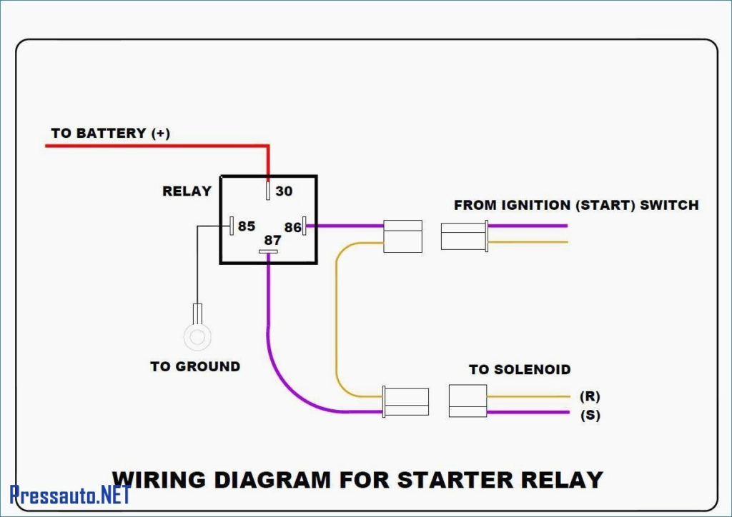
The diagrams for ignition wiring depict the wires used in the vehicle’s power supply. There are generally four colored terminus lines for each component. The red color represents accessories, yellow for the battery and green for the starter solenoid. The “IGN” terminal is used to start the vehicle, controlling the wipers, and for other functions. The diagram shows how you can connect the ACC and ST terminals to the other components.
The terminal BAT is the connector for the battery. The electrical system won’t start in the event that the battery isn’t connected. Additionally, the switch will not turn on without the battery. It is possible to view your wiring diagram to figure out where the batteries of your car are placed. The ignition switch and the battery are connected via accessory terminals. The BAT terminal is connected to the battery.
Some ignition switches include an accessory setting where users can adjust their outputs as well as control them without having to turn on the ignition. Customers may want to use the auxiliary output independently of the ignition. To make use of the auxiliary output, wire the connector using identical colors to the ignition, and connect it to the ACC terminal on the switch. This feature of convenience is fantastic however there’s a differentiator. Most ignition switches come with the ACC position when your vehicle is in ACC mode, and a START position when the switch is in IGN.
Gallery of Ignition Relay Wiring Diagram
Gallery of Ignition Relay Wiring Diagram


