Ignition Starter Switch Wiring Diagram – In the beginning, we’ll look at the different types of terminals on the ignition switch. These include the terminals that are for the Ignition switch, Coil, and Accessory. Once we know the terminals that are utilized then we can determine the various components of the Ignition Starter Switch Wiring Diagram. In addition, we will discuss the function of the Ignition switch and Coil. Then, we’ll turn our attention to Accessory terminals.
Terminals for ignition switch
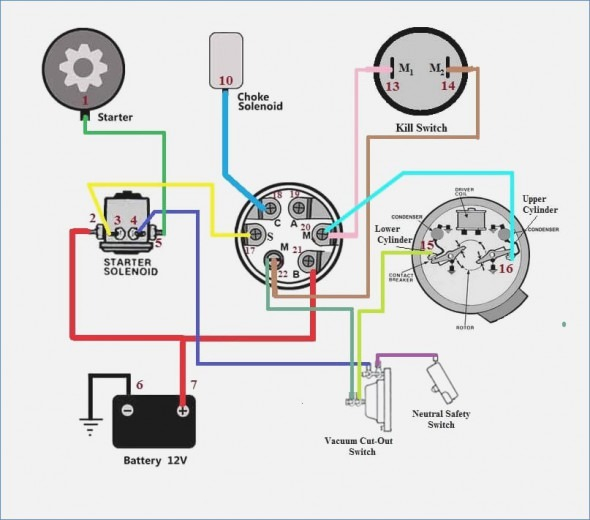
The ignition switch is comprised of three switches that supply the battery’s current to various locations. The first switch provides power to the choke, while the second switch controls the on/off status of the ignition switch. Different manufacturers have their own color-coding system for different conductors that is described in a separate article. OMC utilizes this procedure. A connector can be added to the ignition switch to include the digital Tachometer.
Even though some of the ignition switch terminals may not be original, the numbering of each one might not be in line with the diagram. To ensure that the wires are properly connected to the switch it is recommended to check their continuity. This can be checked using a cheap multimeter. After you’re satisfied with the continuity, you can place the new connector. If your vehicle has an installed ignition switch, the wiring diagram will differ.
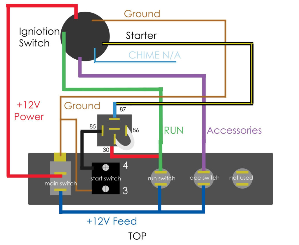
In order to connect the ACC outputs to the auxiliary outputs of your car, you’ll need first know how these two connections work. The ACC and IGN connectors are the default connections of your ignition switch. While the START, IGN, and ACC terminals are the primary connections for the radio or stereo, the START/IGN connections are the most important ones. The ignition switch is accountable to turn the engine of your car on and off. Older cars are identified by the alphabets “ACC”, “ST”, (for individual magneto cables) at the ignition switch terminals.
Terminals for Coil
The first step to determine the type of ignition coil is to comprehend the terminology that is used. The fundamental diagram of ignition wiring shows a number different connections and terminals. There are two primary and secondary connections. Each coil has a specific operating voltage. To determine the type of coil you have, the first step is to check the voltage at the S1 primary terminal. S1 must also be subjected to resistance testing to determine whether it is a Type A or B coil.
The lower-tension side of the coil should be connected to the chassis the negative. This is the base of the wiring for ignition. The high tension part supplies positive power directly to the spark plugs. The aluminum body of the coil has to be linked to the chassis for suppression however it’s not electrically required. The diagram for the ignition wiring will also demonstrate the connections between the positive and negative coil’s terminals. Sometimes, a defective ignition coil can be identified through a scan performed in an auto parts shop.
The black-and-white-striped wire from the harness goes to the negative terminal. The positive terminal receives the white wire and the trace in black. The black wire is connected to the contact breaker. You can remove the black wire from the housing of the plug using a paper clip in case you are uncertain about the connections. Check that the terminals aren’t bent.
Accessory terminals
The diagrams for ignition wiring illustrate the wiring used to power the vehicle’s electrical supply. There are generally four color-coded terminus for each component. Accessories are red, the battery is yellow the starter solenoid green. The “IGN terminal” is used to provide power to the wipers and other operating features. The diagram shows how you can connect the ACC and ST terminals to the other components.
The terminal called BAT is the place where the battery is. Without the battery, the electrical system does not start. Furthermore, the switch won’t begin to turn on. A wiring diagram can show you the location of the battery of your car. Your car’s accessory terminals connect to the ignition switch, as well as the battery. The BAT connector connects to your battery.
Some ignition switches come with an additional “accessory” position, in which users can control their outputs without the ignition. Customers may want to utilize the auxiliary output in addition to the ignition. To make use of the additional output, wire the connector in the same colors as ignition connecting it to the ACC terminal on the switch. Although this is a fantastic feature, there’s something you need to know. Many ignition switches can be configured to be in an ACC position once the car is in the ACC position. They’ll also be in the START mode after the vehicle has been moved into the IGN position.
Gallery of Ignition Starter Switch Wiring Diagram
Gallery of Ignition Starter Switch Wiring Diagram


