Ignition Switch Wiring Diagram For Boat – We will first look at the various types of terminals that are used on the ignition switch. These terminals include the Ignition switch, the Coil as well as the Accessory. After we’ve identified the purpose of these terminals then we can determine the various components in the ignition wiring. We’ll also discuss the roles of both the Ignition Switch and Coil. Then, we’ll talk about the roles of the ignition switch and Coil.
The ignition switch’s terminals
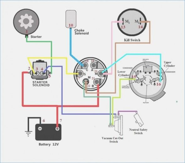
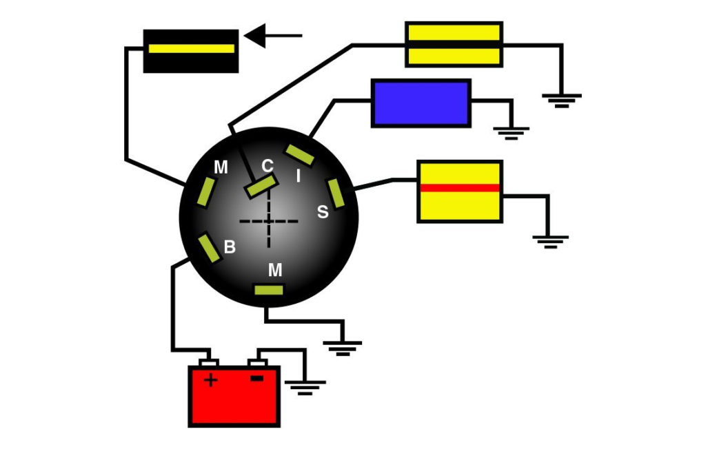
Three switches can be found in an ignition switch. Each of the three switches feeds the battery’s voltage to a variety of destinations. The first switch is utilized to turn on the choke through pushing it, while the third switch is used to control the ON/OFF setting. Different manufacturers employ different colors for different conductors. This is explained in a separate article. OMC follows this scheme. The connector allows for the attachment of a speedometer to the ignition switch.
Although some ignition switch terminals might not be original, the numbers of each one might not match the diagram. The first step is to check the continuity of all wires to ensure they are correctly plugged into the ignition switches. A multimeter is an excellent instrument to verify the continuity. Once you are satisfied that the wires are in good continuity and you are able to connect the new connector. The wiring loom for an ignition switch that is supplied by the manufacturer will differ from the one you have in your car.
It is important to understand how the ACC outputs and the auxiliary outputs function in order to connect them. The ACC and IGN connectors are the standard connections for the ignition switch. Although the START, IGN, and ACC terminals are primary connections for the radio or stereo, the START/IGN terminals are the primary ones. The ignition switch is responsible to turn the engine of your car on and off. The ignition switch terminals on older cars are labeled with the letters “ACC” as well as “ST” (for individual magneto wires).
Terminals for coil
Understanding the terms is the initial step to finding out what kind of ignition coil you own. You’ll see a number of connections and terminals within an ignition wiring schematic that include two primary as well as two secondary. Each coil is equipped with a distinct operating voltage. To determine what kind of coil you’ve got the first step is to determine the voltage at S1, which is the primary terminal. S1 must also be subjected to resistance tests to determine if it is a Type A or B coil.
The low-tension coil side must be connected to the chassis’ minus. This is the ground in the ignition wiring diagram. The high-tension supply provides positively directly to spark plugs. For suppression purposes the coil’s metal body is required to be connected to the chassis. It is not required for electrical use. The diagram of the ignition wiring will also show you the connection of the positive and negative coil’s terminals. In certain instances, you’ll find that the ignition coil is damaged and is easily identified with scanning in an auto parts store.
The black-and-white-striped wire from the harness goes to the negative terminal. The negative terminal is served by the black trace that’s joined to the white wire. The black wire goes to the contact breaker. To check the connections, you can use a paperclip or a pencil to remove them from the plug housing. Check that you don’t bend the connectors.
Accessory terminals
Ignition wiring diagrams depict the various wires utilized to power the various components. In general there are four distinct color-coded terminals for each component. The red color represents accessories, yellow for the battery, and green for the solenoid for starters. The “IGN terminal” is used to run the wipers, as well as other operating functions. The diagram shows the connection to the ACCand ST terminals.
The terminal known as BAT is the location where the battery is. The electrical system will not start in the event that the battery isn’t connected. The switch won’t be able to turn on if the battery isn’t present. To locate your car’s battery look over your wiring diagram. The accessory terminals in your car are connected to the ignition switch, as well as the battery. The BAT terminal is connected to the battery.
Certain ignition switches have an accessory setting where users can adjust their outputs and manage them without having to turn on the ignition. Some customers prefer to make use of an additional output independent of the ignition. Use the secondary output by connecting it to an ACC terminal on the switch with the same colors. This feature of convenience is fantastic, but there is one distinction. Most ignition switches will have an ACC position when the vehicle is in the ACC, but they’ll be in the START position when the vehicle is in IGN.
Gallery of Ignition Switch Wiring Diagram For Boat
Gallery of Ignition Switch Wiring Diagram For Boat


