Ignition Wiring Harley Dual Fire Coil Wiring Diagram – The first step is to look at the different terminals that are used in the ignition switch. These include the terminals that are for the Ignition switch, Coil, and Accessory. After we’ve identified the purpose of the terminals we can identify the various parts of the ignition wiring. In addition, we will discuss the functions of the Ignition switch, as well as the Coil. Then we’ll discuss the Accessory Terminals.
The ignition switch’s terminals
There are three separate switches in an ignition switch that transmit the battery’s current voltage to various places. The first switch powers the choke. The third switch regulates the ON/OFF of the ignition switch. Different manufacturers use their own color-coding systems for the different conductors, that is described in a separate article. OMC uses the same method. The ignition switch is also equipped with a connector for adding an tachometer.
Although the majority of ignition switch terminals aren’t original, the numbering for each might not be consistent with the diagram. First, check the continuity of each wire to ensure that they are properly plugged into the ignition switches. This can be accomplished using a simple multimeter. After you’re satisfied with the continuity, you can place the new connector. If your car has an original factory-supplied ignition switch (or an electrical loom), the wiring loom might differ from the one in the car.
You must first understand the ways in which the ACC outputs and auxiliary outputs work in order to connect them. The ACC and IGN terminals are the default connection on your ignition switch. the START and IGN terminals are the principal connections for radio and stereo. The ignition switch’s function is to turn the engine of your car on and off. Older cars have the ignition switch’s terminals that are labeled “ACC” or “ST” (for individual magnetowires).
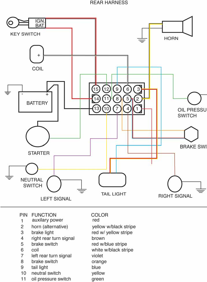
Coil terminals
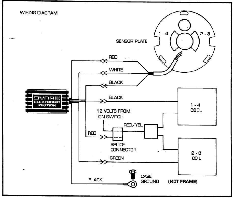
The first step in determining the type of ignition coil is to know the terminology that is used. You’ll see a number of connections and terminals within a basic ignition wiring schematic which includes two primary as well as two secondary. Each coil comes with its own operating voltage. To determine the type of coil you have first, you need to check the voltage at the S1 primary terminal. To determine if the coil is an A, C, or B coil, you must also test S1’s resistance.
The coil’s low-tension side must be connected with the chassis positive. This is also the ground on the wiring diagram for ignition. The high tension side supplies positive directly the spark plugs. The body of the coil has to connect to the chassis to prevent it from being smothered, but it is not electrically essential. The wiring diagram for the ignition will demonstrate how to connect the terminals of either the positive and negative coils. In certain instances you’ll discover that the ignition coil is damaged and can be diagnosed with a scan in an auto parts store.
The black-and-white-striped wire from the harness goes to the negative terminal. Positive terminal gets the second white wire, which includes a black trace. The black wire connects to the contactbreaker. It is possible to remove the black wire from the plug housing with a paper clip If you’re unsure of the connection. It is also important to see that the terminals are not bent.
Accessory terminals
Diagrams of ignition wiring show the different wires used for powering the various components. Each component is equipped with four distinct color-coded connections. Red is used for accessories, yellow is for the battery, while green is the starter solenoid. The “IGN” terminal is used to start the car, control the wipers, and other functions. This diagram shows how to connect ACC and ST terminals with the rest of components.
The terminal BAT is where the battery is. Without the battery the electrical system can not get started. The switch won’t turn off if the battery isn’t there. A wiring diagram can tell you the location of your car’s battery. The accessory terminals in your car are connected to the battery and ignition button. The BAT Terminal is connected to the battery.
Some ignition switches come with a separate “accessory” position, where users can control their outputs without using the ignition. Sometimes, users want to utilize an additional output independent of the ignition. The auxiliary output could be used to connect the connector in the same colors as your ignition and connecting it to the ACC terminal of the switch. While this is an excellent option, there’s a thing you need to know. Most ignition switches are configured to have an ACC status when the car’s in the ACC or START positions.
Gallery of Ignition Wiring Harley Dual Fire Coil Wiring Diagram
Gallery of Ignition Wiring Harley Dual Fire Coil Wiring Diagram


