Jacobs Ignition Wiring Diagram – Let’s begin by looking at the different types of terminals on an ignition switch. These are terminals for the Ignition, Coil, or Accessory. When we have a clear understanding of the purpose of each type of terminal, we are able to determine the components of the ignition wiring. Then, we will discuss the functions for the Ignition switch, as well as the Coil. Next, we’ll discuss the functions of the ignition switch and Coil.
Terminals for ignition switches
An ignition switch is made up of three switches. These are responsible for supplying the battery’s power to several places. The ON/OFF state of the ignition switch is controlled by the second switch, which supplies power to the choke when it is pushed. Different manufacturers have various color codes for the different conductors. This is described in another article. OMC utilizes this system. The connector allows for the attachment of a speedometer the ignition switch.
Although the majority of ignition switch terminals aren’t authentic, the numbering of each one may not be in line with the diagram. Before plugging into the ignition switch, be sure to test the continuity. A multimeter is a good tool to test the continuity. Once you’ve verified that the wires are in good condition, you can then connect the connector. The wiring loom used for an ignition switch that is supplied by the manufacturer will differ from the one you have in your vehicle.
It is essential to know how the ACC outputs and auxiliary outputs work in order to connect them. The ACC, IGN and START terminals are the primary connections to the ignition switch. They also serve as the primary connections to your radio and stereo. The ignition switch acts as the engine’s on/off button. On older vehicles the ignition switch’s terminals are marked with the initials “ACC” as well as “ST” (for individual magnetic wires).
Terminals for Coil
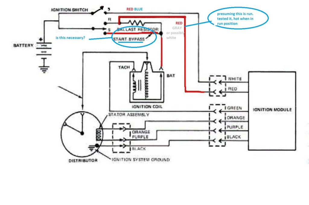
Understanding the terms that is used is the first step towards determining what kind of ignition coil to choose. You will see several connections and terminals within an ignition wiring schematic, including two primary, and two secondary. It is essential to identify the type of coil you are using by testing the voltage on the primary terminal S1. S1 must be examined for resistance to identify if the coil is Type A, B, or C.
The negative of the chassis must be connected to the low-tension side. This is what is known as the ground for the ignition wiring. The high-tension supply supplies the spark plugs with positive electricity directly. The aluminum body of the coil has to be linked to the chassis for suppression but isn’t required. The wiring diagram for the ignition will show you how to connect the terminals of the positive or negative coils. It is possible to find an ignition coil problem that is easily identified by scanning it in the auto parts shop.
The black-and-white-striped wire from the harness goes to the negative terminal. The other white wire is black and connects to the negative terminal. The black wire connects with the contact breaker. To confirm the connections, you can use a paperclip or a pencil to remove them from the plug housing. Check that the terminals aren’t bent.
Accessory Terminals
Diagrams of ignition wiring show the wiring used to power various parts of the vehicle. Typically there are four distinct color-coded terminals for each component. The red color is used for accessories, yellow is for the battery, and green is for the starter solenoid. The “IGN” terminal is used to start the car, operating the wipers and various other functions. The following diagram shows how to connect the ACC terminal as well as the ST terminals to various components.
The terminal known as BAT is the place where the battery is. Without the battery the electrical system will not get started. The switch won’t be able to turn on if the battery isn’t there. You may refer to the wiring diagram if not sure where the batteries of your car are located. Your car’s accessory terminals connect to the ignition switch and the battery. The BAT Terminal is connected to the battery.
Some ignition switches are equipped with an accessory position. This allows users to connect their outputs to another location without having to turn on the ignition. Some customers prefer to make use of an additional output independent of the ignition. For the auxiliary output to be used, plug in the connector in the same color as that of the ignition. Then , connect it to the ACC end of the switch. While this is an excellent option, there’s an significant difference. Most ignition switches will have an ACC position if the car is in the ACC, but they’ll be at the START position when the vehicle is in IGN.
Gallery of Jacobs Ignition Wiring Diagram
Gallery of Jacobs Ignition Wiring Diagram


