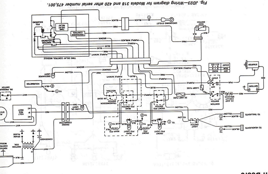
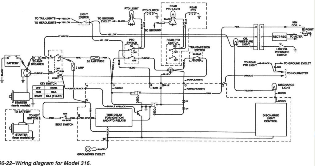
John Deere 318 Ignition Wiring Diagram – Let’s first examine the various terminals that are used in the ignition switch. These terminals are for the Ignition button, Coil and Accessory. Once we know what these kinds of terminals are for, we will proceed to determine the various parts of the John Deere 318 Ignition Wiring Diagram. We’ll also be discussing the function of the Ignition switch, and Coil. After that, we’ll turn our attention to Accessory terminals.
The terminals of the ignition switch
An ignition switch contains three different switches that direct the battery’s current to different destinations. The first one supplies power to the choke whenever it is pushed. The second is the position of the ignition switch’s ON/OFF. Different manufacturers have different color-coding schemes to identify different conductors. We’ll discuss this in another article. OMC utilizes the same system. The ignition switch also includes an option to connect the timer.
Although most ignition switch terminals can be duplicated, the number may not match the diagram. It is important to first verify the continuity of the wires to see if they are connected to the correct ignition switch. This can be done with a multimeter that is inexpensive. When you are satisfied with the integrity of the wires you can connect the new connector. The wiring loom used in an ignition system switch that is supplied by the manufacturer is distinct.
Understanding how ACC outputs are connected to the other outputs in your car is vital. The ACC and IGN connectors are the default connections for your ignition switch. While the START, IGN, and ACC terminals are primary connections for the radio or stereo, the START/IGN connections are the primary ones. The ignition switch turns the car’s engine on and OFF. On older cars, the ignition switch terminals are marked with the initials “ACC”, and “ST” (for individual magnet wires).
Terminals for coil
The first step in determining the type of ignition coil is to comprehend the terms that is used. In a basic ignition wiring diagram, you will see a number of different terminals and connections, including two primary and two secondary. The voltage that operates on each coil is different. Therefore, it is crucial to test the voltage at S1 (primary terminal). S1 should also be tested for resistance in order to identify if the coil is an A, Type B, or an A coil.
The coil with low tension must be connected at the chassis’ less. This is what’s called the ground on the wiring diagram for ignition. The high-tension supply delivers the spark plugs with positive electricity directly. The aluminum body of the coil needs to be linked to the chassis for suppression however it’s not electrically required. The diagram of the ignition wiring will also show you how to connect the positive and negative coil’s terminals. There could be an issue with the ignition coil that is easily identified by looking it up at an auto parts retailer.
The black-and-white-striped wire from the harness goes to the negative terminal. The positive terminal also receives the white wire that is black in its trace. The contact breaker is linked to the black wire. To check the connection, employ a paperclip, or a pencil to lift them out of the housing for the plug. Check that you don’t bend the connectors.
Accessory terminals
The ignition wiring diagrams illustrate the different wires used to provide power to the various parts of the car. Each component has four distinct colored connections. Red stands for accessories, yellow for the battery and green is for the starter solenoid. The “IGN terminal is used for starting the car, operating the wipers and other functions. The below diagram shows how to connect the ACC terminal as well as the ST terminals to various components.
The terminal BAT connects the battery to the charger. Without the battery, the electrical system does not start. Additionally the switch won’t come on. If you’re not sure the exact location where the battery in your car is situated, look at your wiring diagram to figure out the best way to find it. The accessory terminals of your vehicle are connected to the battery and ignition button. The BAT connector is connected to your battery.
Some ignition switches have the “accessory” position that allows users to control their outputs without needing to utilize the ignition. Sometimes, customers want to make use of an additional output that is not connected to the ignition. It is possible to use the auxiliary input by connecting the connector to the ACC terminal. This feature of convenience is fantastic, but there is one distinction. Some ignition switches are programmed to have an ACC location when the car is in the ACC position. They also will be in the START mode when the vehicle has moved into the IGN position.
Gallery of John Deere 318 Ignition Wiring Diagram
Gallery of John Deere 318 Ignition Wiring Diagram


