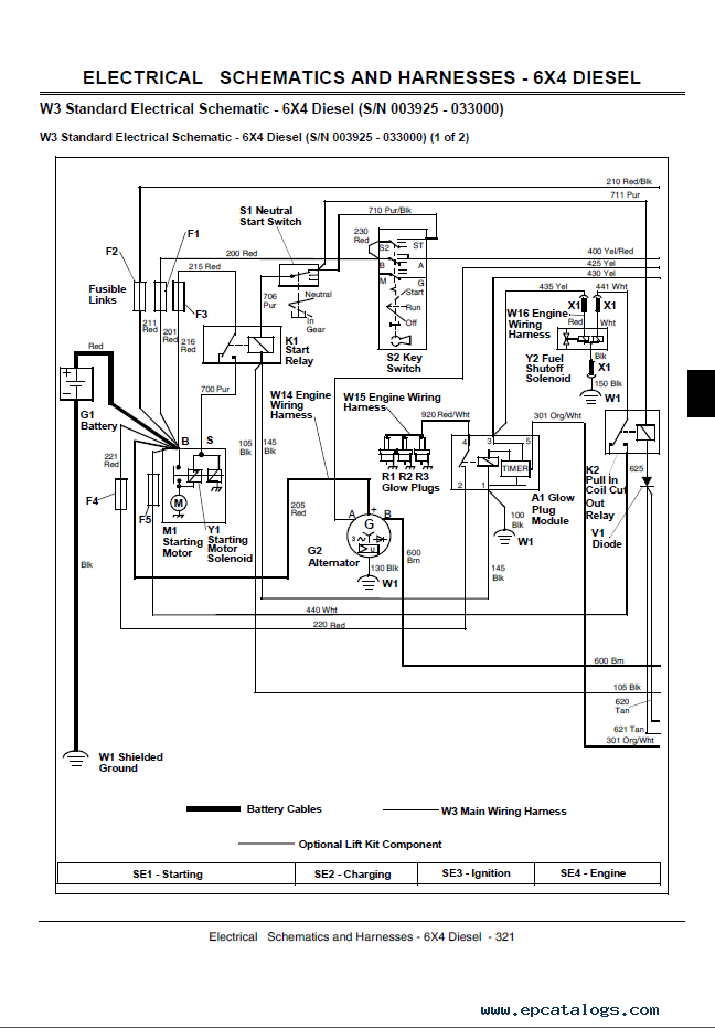
John Deere Gator 4×2 Ignition Wiring Diagram – We will first take a look at the different kinds of terminals on the ignition switch. They are the terminals used that are used for Coil, Ignition Switch, and Accessory. Once we know the purpose of each terminal, we can then determine the components of the ignition wiring. In addition, we will discuss the different functions of the Ignition Switch and the Coil. We’ll then turn our attention to the accessory terminals.
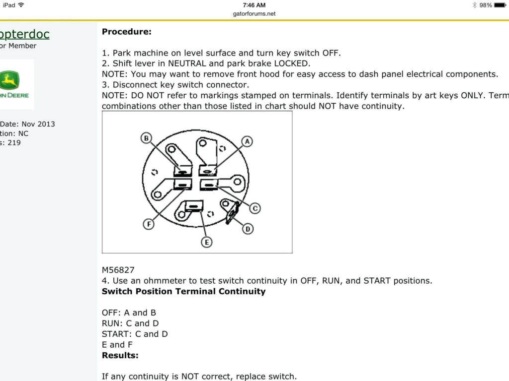
The ignition switch’s terminals
Three switches are found on the ignition switch. Each of the three switches is able to feed the battery’s voltage to several different locations. The first switch supplies the choke with power when pushed, and the second is the ignition switch’s ON/OFF position. Different manufacturers have different color-coding schemes for different conductors. We’ll discuss this in a separate article. OMC utilizes this method. An additional connector is included inside the ignition switch to allow connecting an tachometer.
Although some ignition switch terminals could not be original, the numbers of the terminals may not be in line with the diagram. You should first check the integrity of the wires to ensure that they are connected to the ignition switch correctly. A simple multimeter will aid in this. When you’re satisfied with the continuity of your wires, you will be able to install the new connector. If your vehicle has an installed ignition switch the wiring diagram will differ.
In order to connect the ACC outputs to the auxiliary outputs on your vehicle, you have first know how these two connections work. The ACC, IGN and START terminals are the default connection to the ignition switch. They also function as the primary connections to your radio and stereo. The ignition switch is the engine’s off/on button. In older vehicles, the ignition switch terminals are identified with the alphabets “ACC” as well as “ST” (for individual magnet wires).
Terminals for coil
Understanding the terms used is the initial step towards determining the kind of ignition coil to choose. A basic diagram of the wiring will provide you with a range of terminals and connections. Each coil is operating at a certain voltage. The first step in determining which kind you have is to check the voltage at S1 or the primary terminal. S1 should also undergo resistance testing to determine if it is a Type A or B coil.
The coil with low tension must be connected at the chassis’ plus. This is the ground of the wiring for ignition. The high-tension supply supplies positive directly to spark plugs. The metal body of the coil needs to be connected to the chassis to prevent it from being smothered but is not electrically necessary. The ignition wiring diagram will also outline the connection of the positive coil’s terminals. In certain instances it is recommended to conduct a scan at your local auto parts shop can help you identify malfunctioning ignition coils.
The black-and-white-striped wire from the harness goes to the negative terminal. The positive terminal receives the white wire with a trace in black. The black wire connects to the contact breaker. If you’re not sure about the connections between the twowires, use an old paper clip to take them from the housing of the plug. Be sure that you don’t bend the connectors.
Accessory terminals
The wiring diagrams for the ignition show the different wires that provide power to the various parts of the car. There are generally four colored terminals that correspond to the respective component. The red color is used for accessories and yellow is for the battery, and green is for the solenoid for starters. The “IGN” terminal can be used to start the car, operate the wipers and other functions. This diagram demonstrates how to connect ACC and ST terminals with the other components.
The terminal BAT connects the battery to the charger. The electrical system won’t start when the battery isn’t connected. A dead battery can cause the switch to not turn on. The wiring diagram will tell you the location of the battery of your car. The accessory terminals in your car are connected to the battery as well as the ignition button. The BAT terminal is connected to the battery.
Certain ignition switches come with an additional position in which users can adjust their outputs and control them without needing to use the ignition. Sometimes, users want to make use of an additional output that is not connected to the ignition. The auxiliary output is connected to connect the connector in the same color as your ignition, and then connecting it to the ACC terminal of the switch. This is a useful feature, however there’s one important distinction. A lot of ignition switches can be configured to be in an ACC location when the car is in the ACC position. They also will be in the START position after the vehicle has been moved into the IGN position.
Gallery of John Deere Gator 4×2 Ignition Wiring Diagram
Gallery of John Deere Gator 4×2 Ignition Wiring Diagram


