John Deere Gator Ignition Switch Wiring Diagram – Let’s begin by examining the different kinds and functions of terminals on the ignition switches. These are terminals for the Ignition, Coil, or Accessory. Once we know the purpose of each kind of terminal, we are able to identify the parts of the ignition wiring. We will also cover the roles of both the Ignition Switch and Coil. We will then focus on the accessories terminals.
The terminals of the ignition switch
The ignition switch consists of three switches. These are the ones that supply the battery’s power to various locations. The first switch provides the choke with power when pushed, and the second is the ignition switch’s ON/OFF position. Every manufacturer has its individual color-coding system that we’ll go over in a separate article. OMC follows this scheme. There is a connector in the ignition switch for connecting an to a tachometer.
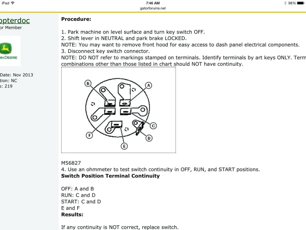
Although some ignition switch terminals could not be authentic, the numbering of each may not match the diagram. To make sure that your wires are plugged in to the switch you must verify their continuity. This can be done with a simple multimeter. After you’re satisfied with the connection it’s time to connect the new connector. If your car is equipped with an original factory-supplied ignition switch (or an electrical loom) The wiring loom may differ from that of your car.
Before connecting the ACC outputs to the auxiliary outputs of your car It is essential to be familiar with the fundamentals of these connections. The ACC/IGN terminals function as the default connections for the ignition switch. The START/IGN terminals connect to the radio or stereo. The ignition switch is the one that turns the car’s engine on and off. Older cars are equipped with ignition switch terminals labeled “ACC” or “ST” (for individual magnetowires).
Terminals for coil
Understanding the terms that is used is the initial step towards determining the kind of ignition coil you need. There are a variety of connections and terminals in a basic ignition wiring schematic that include two primary and two secondary. Each coil has a specific operating voltage. To determine which type of coil you have, the first step is to check the voltage at S1, the primary terminal. S1 should also be checked for resistance to determine whether it’s an A, Type B or A coil.
The low-tension end of the coil needs to be connected to the chassis’ negative. It is also the ground in an ignition wiring diagram. The high-tension side supplies the positive power direct to the spark plugs. It is required to suppress the coil’s metallic body be connected to its chassis, however, it is not necessary. The ignition wiring diagram will also show you the connection of the negative and positive coil’s terminals. Sometimes, a visit to an auto parts shop can diagnose a malfunctioning ignition wire.
The black-and-white-striped wire from the harness goes to the negative terminal. The terminal for the negative is served by the black trace attached to the white wire. The black wire is connected to the contact breaker. To verify the connections between the two wires use a paperclip to remove them out of the housing. Be sure the terminals don’t bend.
Accessory terminals
Ignition wiring diagrams show the various wires used to power the car’s various parts. Each component is equipped with four distinct connections that are color coded. The red symbol represents accessories, yellow represents the battery and green is for the starter solenoid. The “IGN terminal lets you start the car, manage the wipers, and any other features that operate. The diagram shows the connection of the ACCand ST terminals.
The terminal BAT is the connection for the battery. The electrical system won’t start in the event that the battery isn’t connected. The switch will not turn on if the battery isn’t there. To locate your car’s battery look over your wiring diagram. Your car’s accessory terminals are connected to the ignition switch as well as the battery. The BAT terminal connects to the battery.
Some ignition switches feature a separate “accessory” location, which allows users can manage their outputs without using the ignition. Some customers might want to use the auxiliary output separately from the ignition. Use the auxiliary output by connecting it to an ACC terminal on the switch with the same colors. This option is useful however it does have one major differentiator. Most ignition switches are configured to have an ACC position when the vehicle is in the ACC position, while they’re in the START position when the car is in the IGN position.
Gallery of John Deere Gator Ignition Switch Wiring Diagram
Gallery of John Deere Gator Ignition Switch Wiring Diagram


