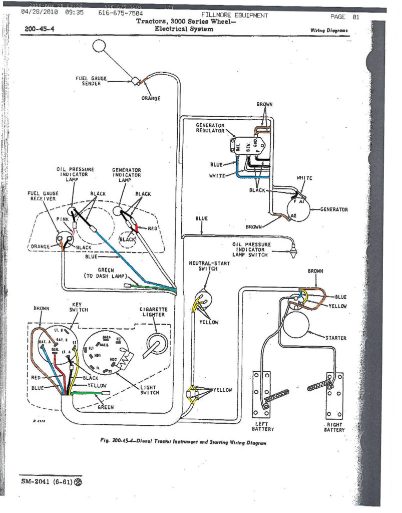
John Deere Ignition Wiring Diagram – We’ll begin by looking at different kinds of terminals that are found in an ignition switch. These terminals are used for the Ignition button, Coil and Accessory. When we have a clear understanding of the purpose of each type of terminal, we are able to identify the parts of the ignition wiring. Then, we will discuss the functions and the Coil. Following that, we’ll shift our attention to Accessory terminals.
Terminals for the ignition switch
Three switches can be found on an ignition switch. Each of these three switches transmits the battery’s current to a variety of places. The ON/OFF setting of the switch that controls the ignition is managed by the third switch, which supplies power to the choke when it’s pulled. Different manufacturers employ various color codes for the different conductors. This is described in another article. OMC utilizes the same system. A connector is also included inside the ignition switch to allow attaching the to a tachometer.
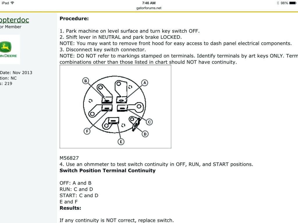
Although most ignition switch terminals can be duplicated, the numbers might not be in line with the diagram. Check the continuity of each wire to ensure they are correctly connected to the ignition switches. This can be done using an inexpensive multimeter. Once you’ve verified that the wires are in good condition, you can install the connector. If your car has an installed ignition switch the wiring diagram will differ.
It is essential to know how the ACC outputs and auxiliary outputs work in order to join them. The ACC/IGN terminals act as the default connections for the ignition switch. The START/IGN terminals connect to the stereo or radio. The ignition switch acts as the engine’s on/off button. The terminals of older cars ignition switches are marked with “ACC” as well as ST (for specific magneto wires).
Terminals for coil
Understanding the terminology utilized is the first step in determining what type of ignition coil. An understanding of the basic wiring diagram for ignition will reveal a variety of connections and terminals. Each coil has a specific operating voltage. To determine which type of coil you’ve got the first step is to check the voltage at the S1 primary terminal. S1 should also be checked for resistance to determine if the coil is a Type B, B or an A coil.
The low-tension side of the coil should be connected to the chassis’ negative. This is also the ground on the ignition wiring diagram. The high tension part supplies positive directly the spark plugs. The metal body of the coil needs to be connected to the chassis to prevent it from being smothered however it isn’t electrically required. The wiring diagram of the ignition will explain how to connect the terminals of the positive and negative coils. In some cases it is recommended to conduct a scan at your local auto parts store can help you identify the malfunctioning ignition coils.
The black-and-white-striped wire from the harness goes to the negative terminal. The negative terminal is served by the trace in black that’s attached to the white wire. The black wire connects to the contact breaker. You can take the black wire from the plug housing with a paper clip If you’re unsure of the connection. Make sure that the terminals don’t bend.
Accessory terminals
Ignition wiring diagrams depict the various wires that are used for powering the different components. Each component is equipped with four distinct color-coded connections. The red color is for accessories, yellow is the battery, and green is the starter solenoid. The “IGN terminal” is used to power the wipers along with other operational functions. The diagram shows the connections between the ACC- and ST terminals.
The terminal called BAT is the place where the battery is. The electrical system can’t be started without the battery. The switch won’t be able to turn on if the battery isn’t there. To find the battery in your car, check your wiring diagram. The accessory terminals of your car connect to the ignition switch as well as the battery. The BAT Terminal is connected to the Battery.
Certain ignition switches have an additional “accessory” location, which allows users can manage their outputs with no ignition. Sometimes, users want to make use of an additional output that is independent of the ignition. In order to use the auxiliary output, wire the connector using identical colors to the ignition and connect it to the ACC terminal on the switch. This is a useful option, but there’s one important difference. A lot of ignition switches can be programmed to have an ACC position when the vehicle is in the ACC position. They’ll also be in START mode once the vehicle is entered the IGN position.
Gallery of John Deere Ignition Wiring Diagram
Gallery of John Deere Ignition Wiring Diagram


