John Deere Lawn Mower Ignition Switch Wiring Diagram – Let’s first examine the various terminals that are used in the ignition switch. These terminals are for the Ignition button, Coil and Accessory. After we’ve identified what these terminals do, we will identify the different parts in the ignition wiring. In addition, we will discuss the functions of both the Ignition Switch and Coil. Then, we’ll talk about the function of the Ignition switch as well as Coil.
Terminals of ignition switch
Three switches are located in an ignition switch. Each of these three switches transmits the battery’s current to various places. The first one is utilized to power the choke by pushing it, while the second is for the ON/OFF setting. Different manufacturers employ different colors for different conductors. This is explained in a separate article. OMC uses this method. The connector allows for the attachment of a speedometer the ignition switch.
Even though most ignition switch terminals don’t carry an original number, they may have a different number. The first step is to check the continuity of each wire to ensure that they are properly plugged into the ignition switches. A multimeter is an excellent tool to check the continuity. After you have verified the integrity of the wires you can then connect the connector. The wiring loom used for an ignition switch that’s supplied by the factory will be different from the one that you have in your vehicle.
The first step is to understand the distinctions between the ACC and the auxiliary outputs. The ACC/IGN connections function as the default connections for the ignition switch. The START/IGN connections connect to the stereo or radio. The ignition switch’s function is to turn the car’s engines on and off. Older cars have the ignition switch’s terminals that are labeled “ACC” or “ST” (for individual magnetowires).
Terminals for coil
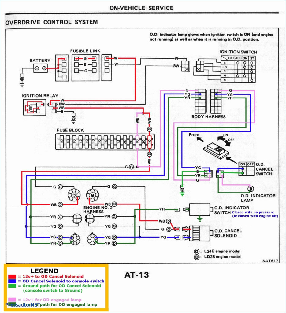
Understanding the terminology utilized is the initial step in finding out the right kind of ignition coil you need. The diagram of the basic ignition wiring shows a number different connections and terminals. There are two primary and secondary connections. The voltage that operates on every coil is different. This is why it is important to first test the voltage at S1 (primary terminal). S1 should also be tested for resistance to determine if it’s a Type B, B, or A coil.
The chassis’ negative must be connected to connect the coil’s low-tension end. This is what you find in the diagram of wiring. The high-tension supply provides the spark plugs with positive electricity directly. It is required to suppress the coil’s metallic body be connected to its chassis but not essential. A wiring diagram can also show the connection between the positive and negative coil terminals. In some instances you’ll discover that an ignition coil that is malfunctioning is easily identified with a scan in an auto parts store.
The black-and-white-striped wire from the harness goes to the negative terminal. The positive terminal is connected to the white wire and the trace in black. The black wire connects to the contactbreaker. If you’re not certain about the connection between both, you can use an old paper clip to take them from the housing of the plug. It’s also essential to make sure the terminals do not bend.
Accessory terminals
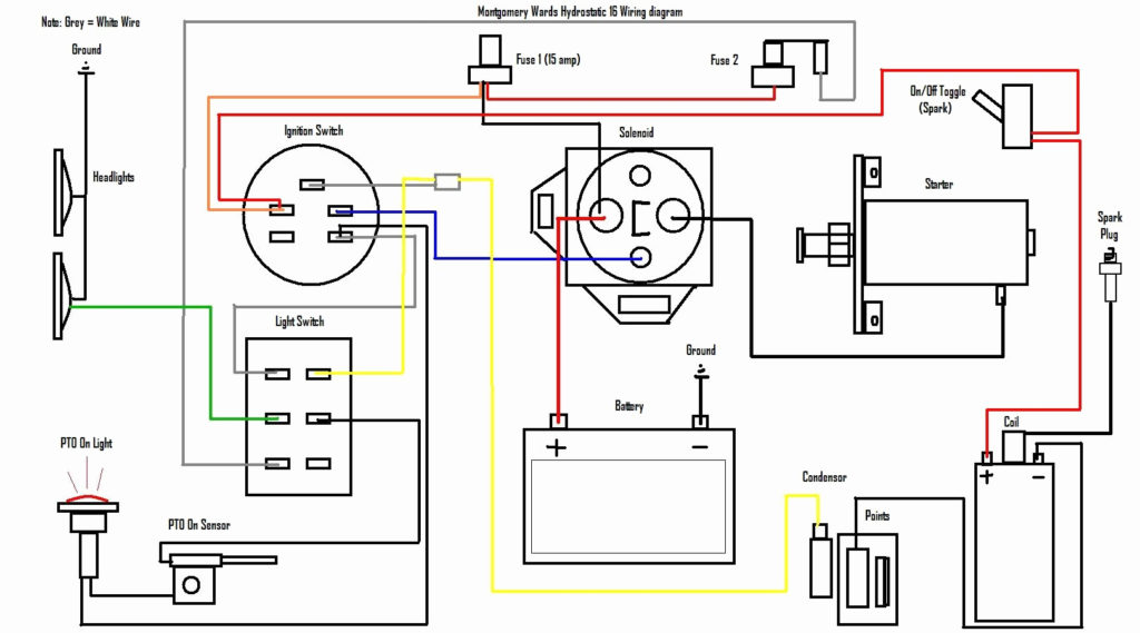
Diagrams of ignition wiring show the different wires used for powering the different components. There are usually four color-coded terminus for each component. Red is for accessories and yellow is for the battery, and green is the solenoid for starters. The “IGN” terminal can be used to turn on the car, operate the wipers and other functions. This diagram demonstrates how to connect ACC and ST terminals to the rest of components.
The terminal BAT connects the battery to the charger. The electrical system cannot begin without the battery. A dead battery can cause the switch to stop turning on. If you don’t know where your car’s battery is situated, you can examine your wiring diagram to figure out where it is. The ignition switch is connected to the car’s battery. The BAT Terminal is connected to the Battery.
Some ignition switches are equipped with an additional position. It allows users to connect their outputs to a different place without having to turn on the ignition. Sometimes, customers wish to use an auxiliary output that is separate from the ignition. For the auxiliary output to be used, wire the connector with the same shade as that of the ignition. Then , connect it to the ACC end of the switch. This is a useful feature, however there’s one important distinction. Most ignition switches are designed to show an ACC status when the car is in either the ACC or START positions.
Gallery of John Deere Lawn Mower Ignition Switch Wiring Diagram
Gallery of John Deere Lawn Mower Ignition Switch Wiring Diagram


