Kawasaki Bayou 300 Ignition Wiring Diagram – We will first look at the various types of terminals that are used on the ignition switch. These terminals serve for the Ignition button, Coil and Accessory. Once we know what these terminals are, we will be able to identify the various parts of the ignition wiring. We’ll also discuss the function of the Ignition switch, and Coil. The next step is to focus on the accessory terminals.
Terminals for ignition switches
Three switches can be found on the ignition switch. Each of these switches feeds the battery’s voltage to several different destinations. The first switch supplies power to the choke when it is pushed. The third is the position of the ignition switch’s ON/OFF. Each manufacturer has its own color-coding system, which we will discuss in another article. OMC follows the same system. There is a connector in the ignition switch for attaching a Tachometer.
While the majority of ignition switch terminals don’t carry an initial number, they could have a different one. Check the continuity of all wires to ensure that they are properly connected to the ignition switches. You can do this with a simple multimeter. Once you’ve verified the integrity of the wires you are able to connect the connector. The wiring loom for an ignition switch that is supplied by the manufacturer will differ from the one you have in your car.
It is essential to know how the ACC outputs and the auxiliary outputs work in order to join them. The ACC and IGN terminals are the default connection on your ignition switch. the START and IGN terminals are the primary connections for the stereo and radio. The ignition switch is the one that turns the engine of your car to and off. On older cars the ignition switch’s terminals are marked with the letters “ACC”, and “ST” (for distinct magnetic wires).
Terminals for coil
To figure out the type of ignition coil, the first step is to learn the terminology. A basic ignition wiring layout will show you a number of terminals and connections. The coils are equipped with a particular operating voltage, and the first step in determining which type you’re using is to test the voltage at S1, the main terminal. S1 should also undergo resistance testing to determine whether it’s an A or B coil.
The low-tension end of the coil should be connected to the chassis the negative. This is the wiring diagram you will see on the wiring diagram. The high-tension side provides positive direct to the sparkplugs. For suppression purposes, the coil’s metal body is required to be connected to the chassis. It is not required to connect electrically. The wiring diagram of the ignition will demonstrate how to connect the terminals of either the positive and negative coils. Sometimes, a check at an auto parts shop can diagnose a malfunctioning ignition wire.
The black-and-white-striped wire from the harness goes to the negative terminal. The positive terminal receives the other white wire and a trace of black. The black wire connects to the contactbreaker. To verify the connections between the two wires, use a paperclip and lift them off the housing. Also, make sure that the connections aren’t bent.
Accessory Terminals
Diagrams of ignition wiring show the various wires that are used for powering the various components. There are typically four terminals with color codes that are connected to the component. Red is for accessories while yellow is the battery, and green is the starter solenoid. The “IGN terminal is used for starting the car, operating the wipers, and for other functions. This diagram demonstrates how to connect ACC and ST terminals to the rest of components.
The terminal BAT is the connection to the battery. The electrical system can’t begin without the battery. A dead battery could make the switch not turn on. A wiring diagram can show you the location of your car’s battery. The accessory terminals of your car are connected to the ignition switch as well as the battery. The BAT terminal is connected to the battery.
Some ignition switches have an “accessory” setting that permits users to control their outputs , without having to use the ignition. Customers may want to use the auxiliary output in addition to the ignition. The auxiliary output can be utilized to connect the connector in the same colors as your ignition, and then attaching it to the ACC terminal of the switch. This is a convenient feature however, it does have one key differentiator. Some ignition switches are programmed to have an ACC location when the car has been moved into the ACC position. They also will be in the START mode when the vehicle has moved into the IGN position.
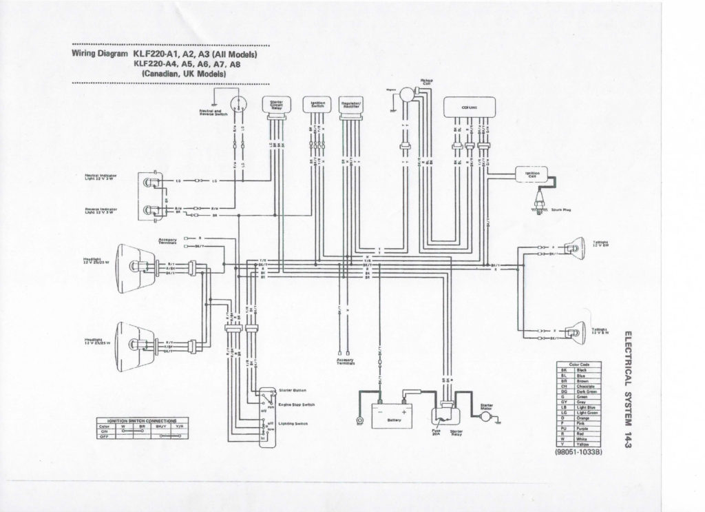
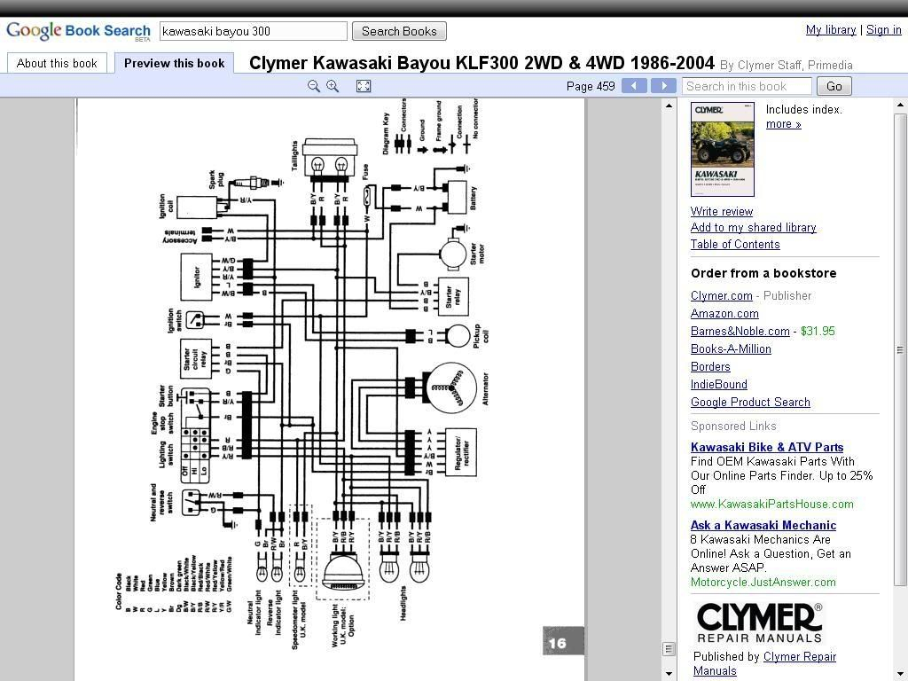
Gallery of Kawasaki Bayou 300 Ignition Wiring Diagram
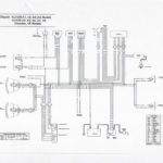
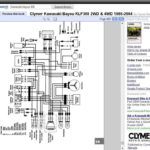
Gallery of Kawasaki Bayou 300 Ignition Wiring Diagram


