Key Switch 5 Prong Ignition Switch Wiring Diagram – The first step is to examine the various terminals on the ignition switch. These include the terminals for the Ignition switch, Coil, and Accessory. When we have a clear understanding of the purpose of each kind of terminal, we can then identify the various components of the ignition wiring. We’ll also discuss the functions and the Coil. We will then discuss the function of the ignition switch and Coil.
Ignition switch terminals
Three switches are located in an ignition switch. Each of the three switches is able to feed the battery’s voltage to several different destinations. The first is utilized to power the choke through pushing it, and the third switch is used to control the ON/OFF setting. Every manufacturer has its individual color-coding system that we’ll discuss in a subsequent article. OMC follows this scheme. The connector allows for the attachment of a speedometer to the ignition switch.
While the majority of ignition switch terminals don’t come in original form, the numbering may not match the diagram. Examine the electrical continuity first to make sure they’re connected correctly to the ignition switch. A simple multimeter will assist you in this. Once you’re satisfied with the continuity it’s time to connect the new connector. If your car has an ignition switch that is installed, the wiring diagram will differ.
In order to connect the ACC outputs to the auxiliary outputs on your vehicle, you have to understand the way these two connections function. The ACC and IGN connectors are the standard connections of your ignition switch. While the START, IGN, and ACC terminals are the primary connections for the radio or stereo, the START/IGN connections are the most important ones. The ignition switch is responsible for turning the car’s engine on and off. The terminals of older cars ignition switches are marked with “ACC” as well as ST (for the individual magneto wires).
Terminals for coil
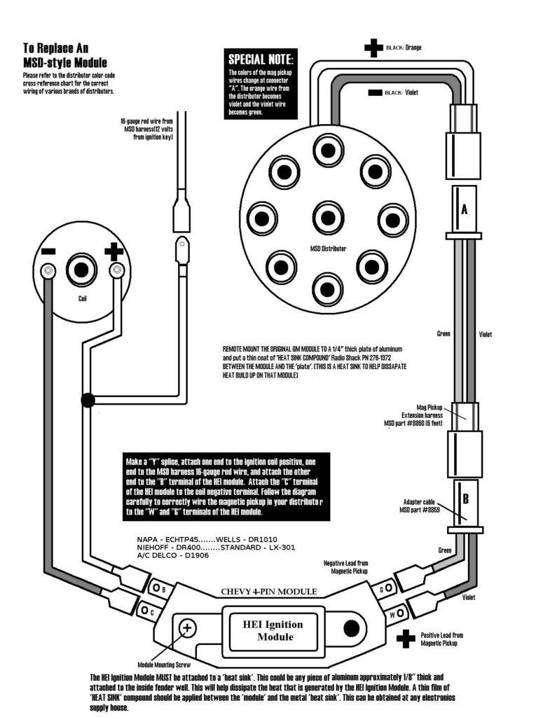
Understanding the terminology used is the first step towards finding out the right kind of ignition coil to choose. There are a variety of connections and terminals within an ignition wiring schematic, including two primary, and two secondary. Each coil operates at a specific voltage. The first step to determine the type you have is to check the voltage on S1, or the primary terminal. S1 must be checked for resistance to identify if the coil is type A, B and/or C.
The coil’s low-tension side must be connected to the chassis’ positive. This is the ground on the diagram of ignition wiring. The high-tension side connects the spark plugs to a positive. The aluminum body of the coil needs to be connected to the chassis to prevent it from being smothered, but it isn’t electrically required. The diagram for the ignition wiring will also demonstrate the connections between the negative and positive coil terminals. In certain instances, you’ll find that an ignition coil that is malfunctioning is easily identified with a scan in an auto parts store.
The black-and-white-striped wire from the harness goes to the negative terminal. The terminal for the negative is served by the black trace attached to the white wire. The black wire connects with the contact breaker. You can examine the connections with a paperclip to remove the wires from the housing. Be sure the terminals aren’t bent.
Accessory Terminals
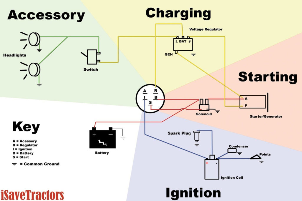
Diagrams of ignition wiring show the wires that supply power to different parts of the vehicle. Each part has four distinct colored connections. For accessories, red is the starter solenoid’s color, yellow is for battery and blue for accessory. The “IGN terminal” is used to run the wipers, along with other operational features. The diagram illustrates the connection between the ACCand ST terminals.
The terminal BAT is the connection to the battery. The battery is essential for the electrical system to begin. The switch also won’t be able to turn on without the battery. A wiring diagram can inform you where to find your car’s battery. The ignition switch is connected to the battery of your car. The BAT terminal is connected to the battery.
Some ignition switches are equipped with an accessory position. It allows users to connect their outputs to a different place without the ignition. Users may wish to use the auxiliary output independently of the ignition. To make use of the auxiliary output, wire the connector in the same colors as the ignition, and connect it to the ACC terminal on the switch. This option is useful, but it has one major differentiator. Most ignition switches will be in an ACC position when the vehicle is in the ACC however they’ll be at the START position if the car is in IGN.
Gallery of Key Switch 5 Prong Ignition Switch Wiring Diagram
Gallery of Key Switch 5 Prong Ignition Switch Wiring Diagram


