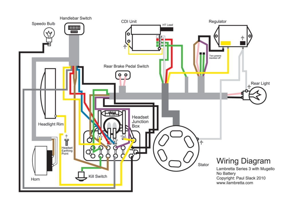
Lambretta Ignition Switch Wiring Diagram – Let’s first examine the different types and purposes of the terminals in the ignition switches. They include terminals for the Ignition switch, Coil, and Accessory. Once we know the terminals used, we can begin to determine the various components of the Lambretta Ignition Switch Wiring Diagram. In addition, we will discuss the roles of the Ignition switch, and Coil. Following that, we’ll shift our attention to Accessory terminals.
Terminals for the ignition switch
An ignition switch is made up of three switches. These are responsible for feeding the battery’s energy to various destinations. The ON/OFF position of the ignition switch is controlled by the first switch, which provides the choke with power when it’s pulled. Different manufacturers utilize their own color-coding method for different conductors which is explained in a different article. OMC uses the same method. There is a connector in the ignition switch to allow attaching an to a tachometer.
Although the majority of ignition switch terminals aren’t original, the numbering for each may not match the diagram. Before plugging into the ignition switch, ensure that you check the continuity. You can check this using a simple multimeter. After you’re sure that the wires are in good order and you are able to connect the new connector. The wiring loom of the ignition system switch supplied by the manufacturer differs.
For connecting the ACC outputs to the auxiliary outputs of your car, you’ll need to first understand how these two connections work. The ACC/IGN connections function as the default connections for the ignition switch. The START/IGN terminals connect to the stereo or radio. The ignition switch switches the engine of your car ON and OFF. On older vehicles the ignition switch’s terminals are identified with the letters “ACC” as well as “ST” (for distinct magnet wires).
Terminals for coil
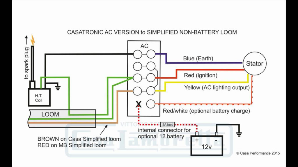
The terms used to define the type and model of the ignition coil is the most important thing. The fundamental diagram of ignition wiring shows a number different connections and terminals. There are two primary and one secondary. Each coil has a specific operating voltage. To determine the type of coil you have the first step is to test the voltage at S1, the primary terminal. S1 should be checked for resistance to determine if the coil belongs to type A, B and/or C.
The coil’s low-tension component must be connected with the chassis positively. This is the ground on the ignition wiring diagram. The high-tension side delivers positive direct to the spark plugs. It is essential to suppress the metallic body of the coil is connected to its chassis, but not essential. The wiring diagram for ignition will also show how to connect the positive coil terminals. Sometimes, an inspection at an auto part store can identify a problem with the ignition wire.
The black-and-white-striped wire from the harness goes to the negative terminal. The negative terminal is served by the black trace joined to the white wire. The black wire connects to the contactbreaker. To check the wires’ connections use a paperclip and remove them from the housing. It is also important to make sure the terminals do not bend.
Accessory Terminals
Diagrams of the ignition wiring show the wires used to supply power to different parts of the vehicle. There are usually four colored terminals that correspond to the respective component. The accessories are colored red, the battery is yellow, the starter solenoid is green. The “IGN” terminal is used to turn on the car , and also to operate the wipers, as well as other operating functions. This diagram demonstrates how to connect ACC and ST terminals with the rest of the components.
The battery is attached to the terminal named BAT. The electrical system is not able to start without the battery. Additionally the switch isn’t turned on. If you don’t know where your car’s battery is situated, you can examine your wiring diagram to figure out where it is. The accessory terminals of your car are connected to the battery and ignition button. The BAT connector is connected to your battery.
Certain ignition switches have an accessory position. This allows users to access their outputs from a different place without having to turn on the ignition. Some customers may prefer to use the auxiliary output in addition to the ignition. To use the auxiliary output, connect the connector with the same colors as ignition, connecting it to the ACC terminal on the switch. This feature is convenient, but it has one key difference. Most ignition switches will have an ACC position when the vehicle is in ACC, but they will be in the START position if the vehicle is in IGN.
Gallery of Lambretta Ignition Switch Wiring Diagram
Gallery of Lambretta Ignition Switch Wiring Diagram


