Lawn Mower Ignition Wiring Diagram – Let’s first examine the different types and functions of the terminals that are found in the ignition switches. These terminals serve for the Ignition button, Coil and Accessory. Once we have established what these kinds of terminals are used for, we will proceed to discover the various components of the Lawn Mower Ignition Wiring Diagram. In addition, we will discuss the functions of the Ignition switch and Coil. We will then discuss the function of the Ignition switch and Coil.
The terminals of the ignition switch
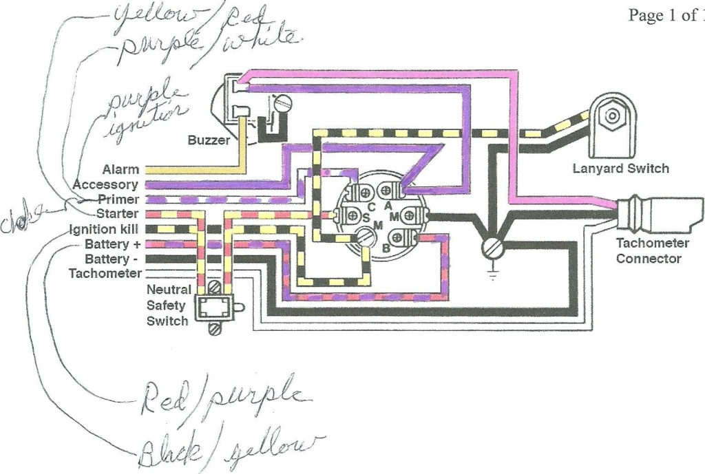
An ignition switch is made up of three different switches. These are responsible for supplying the battery’s energy to various locations. The first switch powers the choke. The second switch is responsible for the ON/OFF function of the ignition switch. Different manufacturers have different color-coding systems to identify different conductors. This will be covered in another article. OMC uses this procedure. An adapter is included on the ignition switch, allowing for the addition of an Tachometer.
Even though some of the ignition switch terminals may not be original, the numbers of each may not match the diagram. First, check the continuity of all wires to ensure they are correctly connected to the ignition switches. This can be accomplished using a simple multimeter. When you’re satisfied with the continuity of your wires, you’ll be able install the new connector. The wiring loom for an ignition switch that’s supplied by the factory will be different from the one you have in your car.
It is essential to know how the ACC outputs and auxiliary outputs function in order to connect them. The ACC and IGN connectors are the standard connections for your ignition switch. Although the START, IGN, and ACC terminals are the primary connections for radios or stereo, the START/IGN connections are the most important ones. The ignition switch switches the car’s engine on and off. The terminals of older vehicles ignition switches are identified with “ACC” as well as ST (for the individual magneto wires).
Terminals for coil
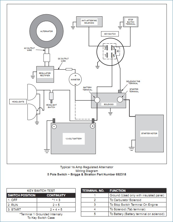
The first step to determine the kind of ignition coil is to know the terms used. You will see several connections and terminals on the basic wiring diagram for ignition which includes two primary as well as two secondary. The coils have a specific operating voltage. The initial method of determining what type you’ve got is to check the voltage at S1, the main terminal. S1 must be tested for resistance in order to identify if the coil is Type A, B, or C.
The low-tension end of the coil should be connected to the chassis’ negative. This is what’s called the ground on the diagram of ignition wiring. The high-tension end supplies positive direct to the sparkplugs. It is essential for the purpose of suppression that the body of the coil’s metal be connected to its chassis but not essential. The wiring diagram will show the connection between the positive and negative coil terminals. In certain instances, you’ll find that a malfunctioned ignition coil can be diagnosed with scanning at an auto parts shop.
The black-and-white-striped wire from the harness goes to the negative terminal. The white wire has a black color and goes to the negative terminal. The black wire is connected to the contact breaker. To verify the connection, make use of a paperclip or pencil to pull them out of the plug housing. Make sure you verify that the connections have not been bent.
Accessory terminals
The ignition wiring diagrams illustrate the different wires that are utilized to power the vehicle’s various parts. In general there are four colors-coded terminals that are used for each component. The red symbol represents accessories, yellow for the battery, and green for the solenoid for starters. The “IGN” terminal is used to start the car, operating the wipers, and for other functions. The diagram below shows how to connect both the ACC terminal and ST terminals to the other components.
The terminal BAT connects the battery to the charger. The electrical system will not start in the event that the battery isn’t connected. The switch also won’t turn on without the battery. You can refer to your wiring diagram if you are not sure where the batteries of your car are located. Your car’s accessory terminals connect to the ignition switch, as well as the battery. The BAT terminal is connected to the battery.
Some ignition switches feature the “accessory” position that permits users to regulate their outputs without having to use the ignition. Some customers prefer to use an auxiliary output that is independent of the ignition. The auxiliary output could be connected to connect the connector in the same colors as your ignition, and then attaching it to the ACC terminal of the switch. Although this is a fantastic feature, there’s something you should know. Most ignition switches are set to have an ACC position when the vehicle is in the ACC position, while they’re set to the START position when the car is in the IGN position.
Gallery of Lawn Mower Ignition Wiring Diagram
Gallery of Lawn Mower Ignition Wiring Diagram


