Lucas Ignition Coil Wiring Diagram – Let’s first examine the various terminals used on the ignition switch. These terminals include the Ignition switch, the Coil and the Accessory. Once we know what these kinds of terminals are We will then discover the various components of the Lucas Ignition Coil Wiring Diagram. We’ll also go over the roles of the Ignition switch and Coil. Then, we’ll talk about the functions of the ignition switch and Coil.
The terminals of the ignition switch
Three switches are found in an ignition switch. Each of these switches is able to feed the battery’s voltage to several different locations. The choke is powered by the first switch. The second switch controls the ON/OFF of the ignition switch. Different manufacturers have different color-coding systems to identify different conductors. We’ll discuss this in a different article. OMC follows this system. An additional connector is included inside the ignition switch for connecting the tachometer.
Even though most ignition switch terminals don’t carry an initial number, they could have a different one. Check the electrical continuity to determine if they’re connected to the ignition switch in the correct way. A simple multimeter will aid in this. After you’re happy with the continuity of your wires, you will be able to install the new connector. If your car has an original factory-supplied ignition switch (or an electrical loom) the wiring loom may differ from the one in your car.
Before connecting the ACC outputs to the auxiliary outputs of your car, it is important to be familiar with the fundamentals of these connections. The ACC and IGN terminals are the default connection on your ignition switch. the START and IGN terminals are the primary connections to the radio and stereo. The ignition switch is responsible for turning the car’s engine to and off. Older cars are identified with the initials “ACC”, “ST”, (for individual magneto cables) at the ignition switch’s terminals.
Terminals for coil
To determine the type of ignition coil, the initial step is to know the terminology. An ignition wiring diagram will show a variety of terminals and connections, including two primary and two secondaries. You need to determine the type of coil you are using by testing the voltage on the primary terminal S1. S1 should also undergo resistance testing to determine whether it’s a Type A or B coil.
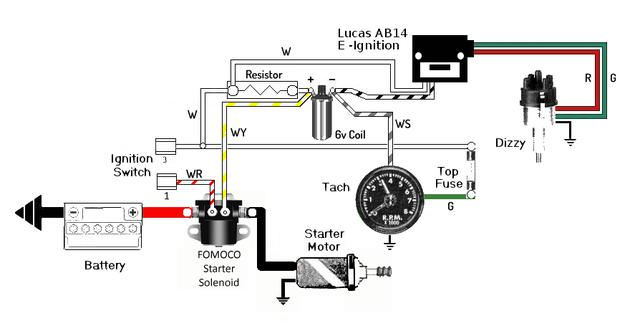
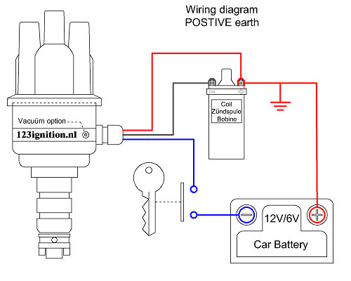
The chassis’ negative should be connected to connect the coil’s low-tension side. This is exactly what you can see on the diagram of wiring. The high-tension side supplies the spark plugs with positive. The body of the coil has to be connected to the chassis to prevent it from being smothered but is not electrically necessary. The diagram of the ignition wiring will also indicate how to connect the positive coil’s terminals. Sometimes, a defective ignition coil is identified with a scan in an auto parts shop.
The black-and-white-striped wire from the harness goes to the negative terminal. The negative terminal is served by the black trace connected to the white wire. The black wire is connected to the contact breaker. To verify the connections between the two wires, use a paperclip to remove them off the housing. Be sure the terminals don’t bend.
Accessory terminals
Diagrams of ignition wiring show the different wires that are used to power the car’s various components. Typically, there are four different colors-coded terminals that are used for each component. Red is for accessories while yellow is the battery, while green is the starter solenoid. The “IGN” terminal can be used to start the car and operate the wipers and other operating features. The diagram shows the connection of the ACCand ST terminals.
The terminal BAT is where the battery is. The electrical system will not start without the battery. The switch won’t turn on if the battery isn’t present. The wiring diagram will show you the location of the battery in your car. The ignition switch and the battery are connected via accessory terminals. The BAT terminal is connected to the battery.
Certain ignition switches come with an accessory setting where users can alter their outputs as well as control them without needing to use the ignition. Sometimes, customers want to make use of the auxiliary output separate from the ignition. The auxiliary output is connected by wiring the connector in the same color as your ignition, and then connecting it to the ACC terminal of the switch. While this is a convenient feature, there is one significant difference. Many ignition switches can be programmed to have an ACC position once the car is in the ACC position. They’ll also be in the START position after the vehicle has been moved into the IGN position.
Gallery of Lucas Ignition Coil Wiring Diagram
Gallery of Lucas Ignition Coil Wiring Diagram


