Lucas Ignition Switch Wiring Diagram – Let’s begin by looking at the various types of terminals in an ignition switch. These are the terminals for the Ignition, Coil, or Accessory. After we’ve established the purpose of these terminals are for then we can identify the different parts of the Lucas Ignition Switch Wiring Diagram. We will also discuss the functions for the Ignition switch, as well as the Coil. We’ll then turn our attention on the accessory terminals.
Terminals for ignition switch
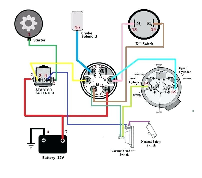
An ignition switch is comprised of three switches. They supply the voltage of the battery to different places. The choke is powered by the first switch. The second switch controls the ON/OFF of the ignition switch. Each manufacturer has its unique color-coding system, which we will discuss in another article. OMC follows this scheme. The ignition switch is also equipped with an option to connect an Tachometer.
While the majority of ignition switch terminals do not have an original number, they might be equipped with a different number. First, check the continuity of each wire to make sure they’re properly connected to the ignition switches. This can be accomplished using a cheap multimeter. Once you’re satisfied about the continuity of your wires, you’ll be able to connect the new connector. The wiring loom for an ignition switch that’s factory-supplied will be different than the one that you have in your vehicle.
It is important to understand how the ACC outputs and the auxiliary outputs work in order to join them. The ACC, IGN and START terminals are the primary connection to the ignition switch. They are also the main connections to the radio and stereo. The ignition switch controls the car’s engine. The terminals of older cars ignition switches are identified by “ACC” as well as ST (for individual magneto wires).
Terminals for coil
Understanding the terms used is the first step in finding out the right kind of ignition coil you need. You’ll see a number of connections and terminals in the basic wiring diagram for ignition which includes two primary as well as two secondary. Each coil is operating at a certain voltage. The first step to determine which type you have is to check the voltage of S1 or the primary terminal. S1 should also be checked for resistance in order to identify if the coil is an A, Type B or an A coil.
The coil with low tension must be connected to the chassis’s less. This is the ground of the wiring for ignition. The high-tension side supplies the spark plugs with positive. To reduce the noise, the coil’s metal body must be connected to the chassis. It is not necessary to electrically connect. A wiring diagram can also show the connection between the positive and negative coil terminals. In certain instances it is recommended to conduct a scan at your local auto parts shop will help identify defective ignition coils.
The black-and-white-striped wire from the harness goes to the negative terminal. The terminal for the negative is served by the black trace attached to the white wire. The black wire connects to the contact breaker. To verify the connections, you can employ a paperclip, or a pencil to remove them of the plug housing. Make sure the terminals aren’t bent.
Accessory Terminals
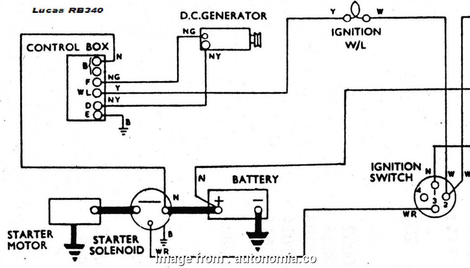
Diagrams of ignition wiring show the wires used to power the vehicle’s electrical supply. There are generally four colored terminals for each component. Red refers to accessories, yellow to the battery and green the starter solenoid. The “IGN” terminal can be used to start the car, control the wipers, and other features. The following diagram shows how to connect the ACC terminal as well as the ST terminals to various components.
The battery is attached to the terminal named BAT. The electrical system will not start without the battery. In addition, the switch will not begin to turn on. You can refer to your wiring diagram if uncertain about where the car’s batteries are located. The accessory terminals in your car are connected with the battery and the ignition button. The BAT terminal is connected to the battery.
Some ignition switches come with an additional position. This lets users connect their outputs to a different location without having to turn on the ignition. Sometimes, a customer wants to utilize an auxiliary output that is separate from the ignition. You can utilize the secondary input by connecting the connector to the ACC terminal. This option is useful however it does have one major difference. The majority of ignition switches are designed to display an ACC status when the vehicle is in either the ACC or START position.
Gallery of Lucas Ignition Switch Wiring Diagram
Gallery of Lucas Ignition Switch Wiring Diagram


