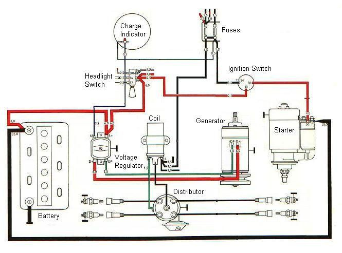
Mahindra Tractor Ignition Switch Wiring Diagram – Let’s start by looking at the different types of terminals in an ignition switch. These terminals include the Ignition switch and Coil and the Accessory. Once we know which terminals are used then we can identify the different components of the Mahindra Tractor Ignition Switch Wiring Diagram. In addition, we will discuss the roles of the Ignition switch, and Coil. After that we will move on to the Accessory Terminals.
Terminals for ignition switch
An ignition switch contains three separate switches that feed the battery’s current to various destinations. The choke is powered by the first switch. The third switch regulates the ON/OFF of the ignition switch. Different manufacturers use different color codes for different conductors. This is explained in a different article. OMC utilizes this method. The ignition switch comes with an adapter for the addition of an timer.
While most ignition switch terminals may not be original, the numbering for each one may not be in line with the diagram. Before you plug into the ignition switch be sure to test the continuity. This can be checked with a simple multimeter. When you’re satisfied with the integrity of your wires, you will be able install the new connector. The wiring loom used in an ignition system switch that is supplied by the manufacturer differs.
To connect the ACC outputs to the auxiliary outputs on your vehicle, you have first know the way these two connections function. The ACC terminals and IGN terminals serve as the primary connections to the ignition switch. The START and IGN connections are the main connections for stereo and radio. The ignition switch operates the engine’s switch to turn off or on. The terminals for the ignition switch on older cars are identified with the alphabets “ACC” and “ST” (for each magneto wires).
Terminals for coil
Understanding the terms is the first step to knowing what type of ignition coil you have. In a simple ignition wiring diagram there are a number of different terminals and connections, including two primary and two secondary. The coils have a specific operating voltage. The first method of determining what type you’re using is to test the voltage at S1, the main terminal. S1 must also go through resistance testing to determine if it is an A or B coil.
The lower-tension side of the coil needs to be connected to the chassis the negative. This is the ground in the diagram of the ignition wiring. The high-tension side supplies the positive power directly to the spark plugs. The aluminum body of the coil needs to be linked to the chassis for suppression but isn’t required. The diagram of the ignition wiring will also reveal how to connect the positive and negative coil’s terminals. In certain instances it is recommended to conduct a scan at your local auto parts shop will be able to diagnose the malfunctioning ignition coils.
The black-and-white-striped wire from the harness goes to the negative terminal. The negative terminal is served by the trace in black that’s attached to the white wire. The black wire connects to the contact breaker. To confirm the connection, make use of a paperclip or pencil to remove them from the plug housing. It’s also crucial to make sure that the terminals do not bend.
Accessory terminals
The wiring diagrams for the ignition show the various wires that provide power to the various parts of the car. There are generally four colors-coded terminus of each part. The accessories are red and the battery yellow and the starter solenoid green. The “IGN terminal is used for starting the vehicle, controlling the wipers, and for other functions. The diagram shows the connections of the ACCas well as ST terminals.
The terminal BAT connects the battery to the charger. The battery is necessary to allow the electrical system to begin. The switch also won’t start without the battery. A wiring diagram can tell you the location of your car’s battery. The ignition switch is linked to the car’s battery. The BAT terminal is connected to the battery.
Some ignition switches include an accessory setting where users can adjust their outputs and control them without the need to use the ignition. Sometimes, a customer wants to utilize the auxiliary output separate from the ignition. It is possible to use the additional input by connecting it to the ACC terminal. This is a convenient feature however it does have one key difference. Many ignition switches can be configured to be in an ACC position when the vehicle has been moved into the ACC position. They also will be in the START position when the vehicle has entered the IGN position.
Gallery of Mahindra Tractor Ignition Switch Wiring Diagram
Gallery of Mahindra Tractor Ignition Switch Wiring Diagram


