Mallory Electronic Ignition Wiring Diagram – First, we will examine the various types of terminals in the ignition switch. These include terminals for Coil, Ignition Switch, and Accessory. Once we have identified what these terminals do, we will identify the different parts in the ignition wiring. In addition, we will discuss the roles of the Ignition switch, as well as the Coil. After that, we will concentrate on the accessories terminals.
Terminals for ignition switch
An ignition switch has three switches. They feed the voltage of the battery to different places. The first one supplies power to the choke whenever it is pushed. The second is the ignition switch’s ON/OFF position. Different manufacturers have different colors for different conductors. This is described in a separate article. OMC uses this method. The adapter is attached to the ignition switch, allowing the installation of the tonometer.
Although the majority of ignition switch terminals are duplicated, the numbers might not match the diagram. Before plugging into the ignition switch make sure to check the continuity. This can be accomplished using a simple multimeter. When you are happy with the continuity of the wires, it is time to connect the new connector. If you’re using an ignition switch supplied by the manufacturer, the wiring loom is different from that you have in your car.
First, understand the differences between the ACC and auxiliary outputs. The ACC, IGN and START terminals are the default connection to the ignition switch. They also function as the main connections to the radio and stereo. The ignition switch regulates the engine in your car. The terminals for the ignition switch on older cars are identified with the alphabets “ACC” and “ST” (for the individual magneto wires).
Terminals for coil
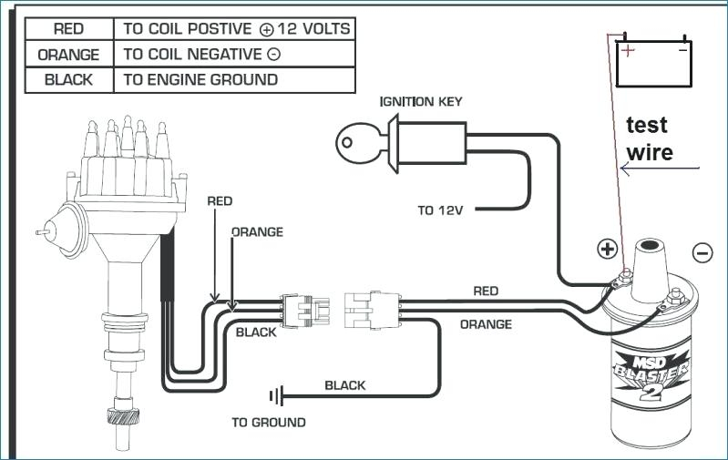
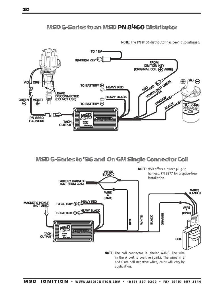
The first step in determining the kind of ignition coil is to understand the terms that is used. The fundamental diagram of ignition wiring illustrates a variety of connections and terminals. There are two primary and one secondary. The coils have a specific operating voltage. The initial method of determining what type you’re using is to test the voltage on S1, the primary terminal. To determine if it is a Type A, C or B coil you should also test S1’s resistance.
The chassis’ negative needs to be connected to the low-tension side. This is exactly what you can see in the diagram of wiring. The high-tension supply delivers positively directly to spark plugs. It is essential to suppress the metallic body of the coil is connected to its chassis however it isn’t essential. You will also see the connections of the negative and positive coil’s terminals on the ignition wiring diagram. In some cases you’ll discover that the ignition coil is damaged and is identified by scanning at an auto parts shop.
The black-and-white-striped wire from the harness goes to the negative terminal. Positive terminal gets the second white wire, which includes a black trace. The contact breaker is linked to the black wire. To check the connections between the two wires employ a paperclip to remove them out of the housing. It’s also crucial to make sure that the terminals aren’t bent.
Accessory terminals
The diagrams for ignition wiring depict the wires used in the vehicle’s power supply. There are generally four colored terminals that correspond to the component. Red is for accessories and yellow is for the battery, and green is the solenoid for starters. The “IGN” terminal is used to start the car , and also to operate the wipers as well as other operational functions. The diagram illustrates the connection to the ACCand ST terminals.
The terminal BAT connects the battery to the charger. The electrical system won’t start without the battery. A dead battery could make the switch stop turning on. You can view your wiring diagram to determine where the batteries of your car are located. The ignition switch is connected to the car’s battery. The BAT terminal is connected to the battery.
Some ignition switches come with an additional “accessory position” that lets users adjust their outputs independently of the ignition. Sometimes, customers wish to utilize the auxiliary output separate from the ignition. To make use of the auxiliary output, wire the connector with the same colors as ignition, and connect it to the ACC terminal on the switch. Although this is a great feature, there’s one thing you should know. Many ignition switches can be set to have an ACC position when the vehicle has moved into the ACC position. They will also be in the START position once the vehicle is moved into the IGN position.
Gallery of Mallory Electronic Ignition Wiring Diagram
Gallery of Mallory Electronic Ignition Wiring Diagram


