Mazda 3 Ignition Coil Wiring Diagram – The first step is to look at the different terminals used on the ignition switch. The terminals are the Ignition switch as well as the Coil and the Accessory. After we’ve established what these kinds of terminals are for then we can determine the various parts of the Mazda 3 Ignition Coil Wiring Diagram. In addition, we will discuss the roles of the Ignition switch, as well as the Coil. Then, we will focus on the accessories terminals.
Terminals for ignition switch
There are three separate switches on the ignition switch, and they transmit the battery’s current voltage to several different places. The first switch is utilized to power the choke through pushing it, while the third switch is used to control the ON/OFF position. Different manufacturers have their own color-coding system for different conductors which is documented in another article. OMC follows this procedure. There is a connector inside the ignition switch for attaching the Tachometer.
While most ignition switch terminals may not be original, the numbering for each might not be consistent with the diagram. To ensure that the wires are correctly connected to the ignition switch you should check their continuity. A multimeter is a great tool to test the continuity. When you’re satisfied with the continuity of the wires, then you’ll be able to connect the new connector. If your vehicle has an original factory-supplied ignition switch (or an electrical loom), the wiring loom might differ from that in your vehicle.
The first step is to understand the distinctions between the ACC and auxiliary outputs. The ACC, IGN and START terminals are the primary connection to the ignition switch. They are also the primary connections to the radio and stereo. The ignition switch is responsible to turn the engine of your car on and off. On older cars the terminals of the ignition switch are marked with the initials “ACC” as well as “ST” (for the individual magnetic wires).
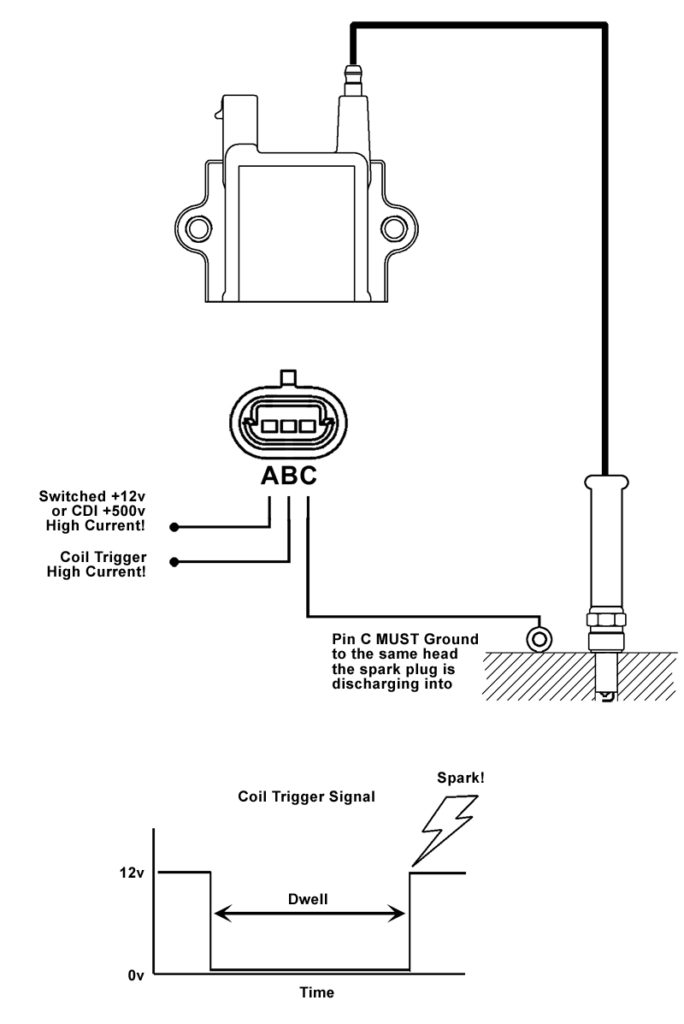
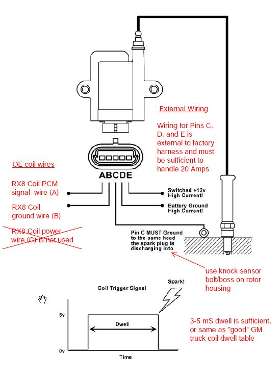
Terminals for coil
Understanding the terms is the initial step towards finding out what kind of ignition coil you have. A simple diagram of the wiring will display a range of connections and terminals, which include two primary terminals and two secondary. Each coil has a specific operating voltage. To determine which type of coil you have, the first step is to determine the voltage at the S1 primary terminal. S1 must be checked for resistance to determine if the coil is type A, B or C.
The coil’s low-tension side should be connected at the chassis’ plus. This is the wiring diagram you will find in the diagram of wiring. The high tension side supplies positive power directly to the spark plugs. It is necessary for the purpose of suppression that the body of the coil’s metal be connected to its chassis however, it is not necessary. The wiring diagram of the ignition will explain how to connect the terminals of either the positive or negative coils. In some cases scanning your local auto parts shop can help you identify malfunctioning ignition coils.
The black-and-white-striped wire from the harness goes to the negative terminal. Positive terminal receives a second white wire, which has a black trace. The contact breaker is connected to the black wire. You can examine the connections using a paperclip to take the wires out of the housing. It is also important to make sure the terminals do not bend.
Accessory terminals
Diagrams of ignition wiring show the wires that supply power to different parts of the vehicle. There are usually four color-coded terminals that correspond to each component. For accessories, red is for starter solenoid, yellow for battery and blue for accessory. The “IGN terminal lets you start your car, operate the wipers, or any other functions. The following diagram shows how to connect both the ACC terminal and ST terminals to other components.
The terminal BAT connects the battery to the charger. The battery is vital for the electrical system to start. Also, the switch won’t start without the battery. To find your car’s battery look over your wiring diagram. The accessory terminals of your car are connected to the ignition switch as well as the battery. The BAT terminal is connected to the battery.
Certain ignition switches have an additional position. It allows users to access their outputs from a different location without having to turn on the ignition. Sometimes, customers may wish to use the auxiliary input independently of the ignition. The auxiliary output could be utilized by wiring the connector with the same color as your ignition and connecting it to the ACC terminal of the switch. This is a great option, but there’s one important difference. Many ignition switches can be configured to be in an ACC position once the car has been moved into the ACC position. They will also be in the START position after the vehicle has been moved into the IGN position.
Gallery of Mazda 3 Ignition Coil Wiring Diagram
Gallery of Mazda 3 Ignition Coil Wiring Diagram


