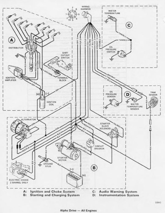
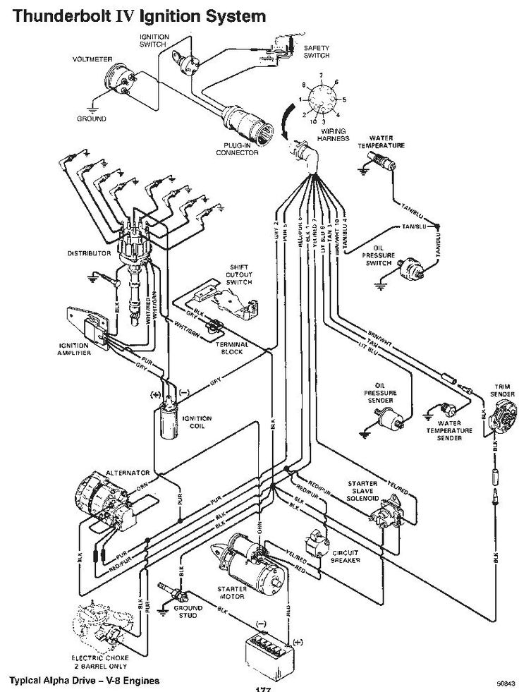
Mercruiser 5.7 Thunderbolt Ignition Wiring Diagram – Let’s first look at the different terminals used on the ignition switch. They are the terminals used for Coil, Ignition Switch, and Accessory. After we’ve identified the purpose of these terminals, we can recognize the various parts of the ignition wiring. We will also talk about the functions as well as the Coil. Following that, we’ll shift our attention to the Accessory terminals.
Terminals of ignition switch
An ignition switch is composed of three switches. These are responsible for supplying the battery’s power to several locations. The first one is used to turn on the choke by pushing it, and the second is for the ON/OFF position. Different manufacturers use different color codes for various conductors. This is described in a separate article. OMC utilizes this method. A connector is also included inside the ignition switch to allow attaching a to a tachometer.
While the majority of the ignition switch terminals may not be original, the numbering for each might not be consistent with the diagram. Check the electrical continuity first to make sure they’re connected correctly to the ignition switch. A cheap multimeter can assist you in this. Once you’re satisfied with the quality of the connection it’s time to connect the new connector. The wiring loom used in a factory-supplied ignition system switch is different.
You must first understand how the ACC outputs and the auxiliary outputs work in order to connect them. The ACC and IGN terminals are the default connections on your ignition switch. the START and IGN terminals are the main connections for the stereo and radio. The ignition switch switches the engine of your car ON and off. Older vehicles are identified with the letters “ACC”, “ST”, (for individual magneto cables) on their ignition switch’s terminals.
Coil terminals
Understanding the terminology is the initial step towards finding out what kind of ignition coil you own. There are a variety of connections and terminals within a basic ignition wiring schematic that include two primary as well as two secondary. Each coil operates at a specific voltage. The first step to determine which type you have is to check the voltage at S1 or the primary terminal. S1 must also go through resistance testing to determine if it are a Type A or B coil.
The coil’s low-tension side must be connected to the chassis positively. This is what’s called the ground in the diagram of the ignition wiring. The high-tension part supplies positive direct to the sparkplugs. It is required to suppress the body of the coil’s metal be connected to its chassis however it isn’t essential. The diagram of the ignition wiring will also reveal the connection of the positive and negative coil terminals. Sometimes, a damaged ignition coil is identified by a scan done in an auto parts shop.
The black-and-white-striped wire from the harness goes to the negative terminal. The white wire also is black with a trace, and connects to the positive terminal. The black wire connects with the contact breaker. To check the connections between the two wires, use a paperclip to lift them out of the housing. Check that you don’t bend the connectors.
Accessory terminals
The ignition wiring diagrams illustrate the various wires utilized to power the vehicle’s various parts. There are generally four colored terminus lines for each component. The red color is for accessories, yellow to the battery and green for the starter solenoid. The “IGN terminal is used to start the car, operating the wipers and various other functions. The following diagram illustrates how to connect the ACC terminal and ST terminals to the other components.
The terminal BAT is the connector for the battery. Without the battery the electrical system can not get started. Additionally, the switch will not start without the battery. It is possible to look up your wiring diagram to figure out where the batteries of your car are located. The accessory terminals in your car are connected to the ignition switch, as well as the battery. The BAT terminal connects to the battery.
Some ignition switches have an “accessory” setting that allows users to control their outputs , without having to use the ignition. Sometimes, customers may wish to use the auxiliary input separately from the ignition. To use the auxiliary output, connect the connector in the same colors as the ignition connecting it to the ACC terminal on the switch. While this is a convenient feature, there’s one significant difference. Most ignition switches are configured to display an ACC status when the car is in the ACC or START position.
Gallery of Mercruiser 5.7 Thunderbolt Ignition Wiring Diagram
Gallery of Mercruiser 5.7 Thunderbolt Ignition Wiring Diagram


