Mercruiser Ignition Wiring Diagram – Let’s first take a look at the different types of terminals on the ignition switch. These terminals include the Ignition switch and Coil and the Accessory. After we’ve identified the purpose of these terminals, we will identify the different parts in the ignition wiring. In addition, we will discuss the different functions of the Ignition Switch and Coil. Then we’ll discuss the Accessory Terminals.
The ignition switch’s terminals
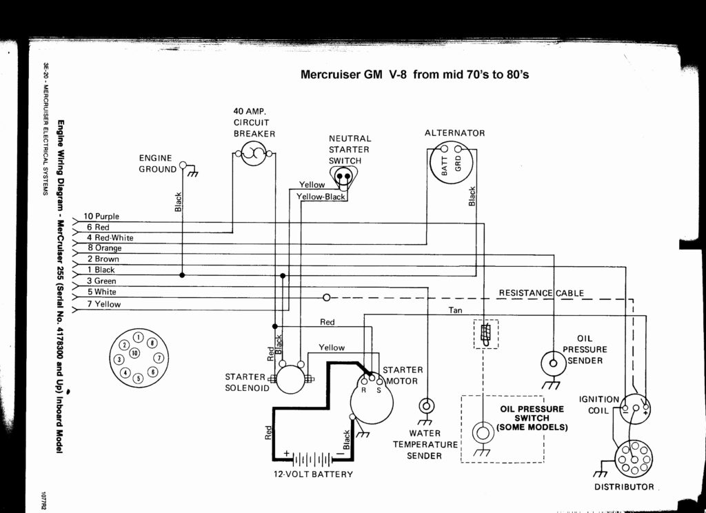
An ignition switch has three separate switches that feed the battery’s power to various destinations. The first switch is the one that supplies power to the choke, while the second toggles the state of the switch. Different manufacturers have distinct colour-coding systems that correspond to the conductors. OMC uses this system. The ignition switch comes with an option to connect the Tachometer.
Although many ignition switch terminals do not have the original design The numbering might not be in line with the diagram. Before you plug into the ignition switch, ensure that you check the continuity. A multimeter that is inexpensive can aid in this. Once you’re satisfied with the quality of the connection then you can connect the new connector. If your vehicle is equipped with an ignition switch that is installed, the wiring diagram will differ.
The first step is to understand the distinctions between ACC and auxiliary outputs. The ACC and IGN terminals are the default connections on your ignition switch. the START and IGN terminals are the primary connections for stereo and radio. The ignition switch switches the engine of your car ON and off. On older vehicles the terminals of the ignition switch are identified with the initials “ACC”, and “ST” (for individual magnet wires).
Terminals for coil
The terminology used to determine the kind and model of the ignition coil is the first thing. You’ll see a number of connections and terminals within an ignition wiring schematic that include two primary as well as two secondary. You must determine the kind of coil you are using by testing the voltage at the primary terminal S1. To determine if it is a Type A, C or B coil it is recommended to also test S1’s resistance.
The chassis’ negative needs to be connected to the low-tension side. This is also the ground on the ignition wiring diagram. The high-tension side connects the spark plugs to a positive. To prevent noise, the coil’s metal body must be connected to chassis. It is not required to connect electrically. The diagram of the ignition wiring will also demonstrate the connections between the negative and positive coil’s terminals. In certain cases scanning your local auto parts shop will be able to diagnose defective ignition coils.
The black-and-white-striped wire from the harness goes to the negative terminal. The other white wire has a black trace on it, and it goes to the positive terminal. The black wire connects to the contactbreaker. To verify the connection, employ a paperclip, or a pencil to lift them out of the housing for the plug. Also, ensure that the terminals are not bent.
Accessory Terminals
Diagrams of ignition wiring depict the wires that are used in the power supply of the vehicle. There are usually four colored terminals that correspond to each component. The accessories are red and the battery yellow the starter solenoid green. The “IGN” terminal is used to start the vehicle, controlling the wipers, and for other functions. The diagram shows how you can connect the ACC and ST terminals to the rest of the components.
The battery is connected to the terminal called BAT. The battery is necessary to allow the electrical system to get started. Also, the switch won’t be able to turn on without the battery. The wiring diagram will inform you where to find your car’s battery. The accessory terminals in your vehicle are connected to the battery and the ignition switch. The BAT Terminal is connected to the battery.
Some ignition switches have the “accessory” position that permits users to regulate their outputs without having to use the ignition. Users may wish to utilize the auxiliary output independently of the ignition. To make use of the auxiliary output, connect the connector in the same colors as ignition, connecting it to the ACC terminal on the switch. Although this is a great feature, there’s one thing you should know. The majority of ignition switches are configured to show an ACC status when the vehicle is at either the ACC or START position.
Gallery of Mercruiser Ignition Wiring Diagram
Gallery of Mercruiser Ignition Wiring Diagram


