Mercury Thunderbolt Ignition Wiring Diagram – Let’s start by looking at the different kinds of terminals that are found on an ignition switch. These terminals serve for the Ignition button, Coil and Accessory. Once we know the purpose of these terminals, we will determine the various components in the ignition wiring. Then, we will discuss the roles of the Ignition switch and the Coil. The next step is to focus to the accessory terminals.
The terminals of the ignition switch
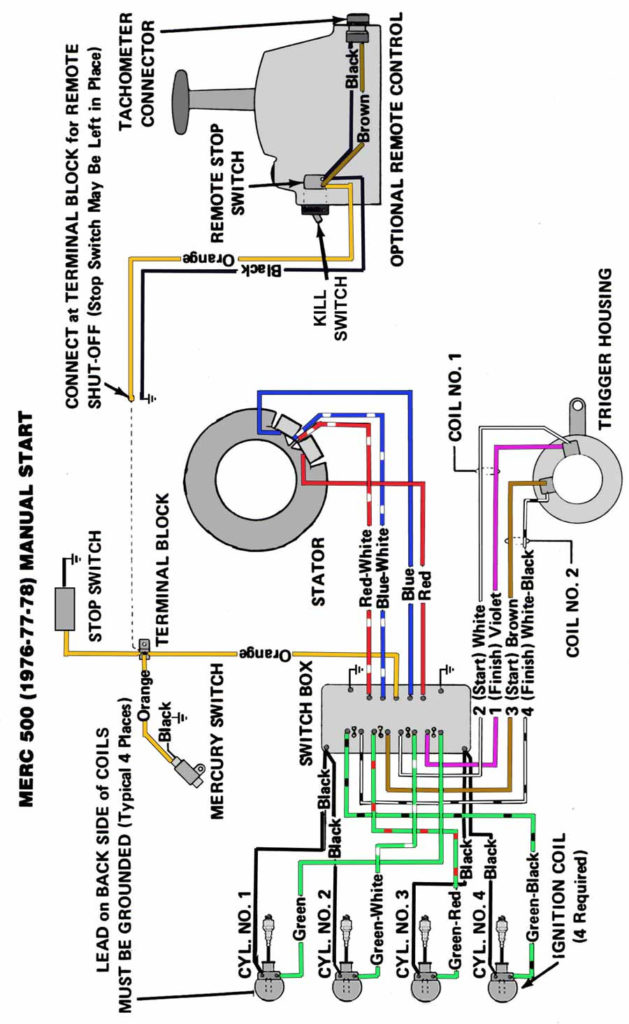
The ignition switch has three switches. They feed the voltage of the battery to different locations. The choke is powered by the first switch. The third switch regulates the ON/OFF function of the ignition switch. Each manufacturer has its individual color-coding system that we will discuss in another article. OMC utilizes the same system. An additional connector is included in the ignition switch for attaching an Tachometer.
Even though the majority of ignition switch terminals do not have the original design however, the numbers may not be in line with the diagram. Check the continuity of all wires to ensure they are correctly plugged into the ignition switches. A multimeter is a great instrument to verify the continuity. Once you’re satisfied about the integrity of your wires, you’ll be able install the new connector. If your car has an original factory-supplied ignition switch (or an electrical loom) The wiring loom might differ from the one in your car.
Before connecting the ACC outputs to your car’s auxiliary outputs it is crucial to know the fundamentals of these connections. The ACC/IGN terminals function as the default connections for the ignition switch. The START/IGN connections connect to the radio or stereo. The ignition switch is accountable to turn the engine of your car on and off. The terminals of the ignition switch on older cars are identified with the letters “ACC” as well as “ST” (for individual magneto wires).
Terminals for coil
The first step to determine the kind of ignition coil is to understand the terms used. A simple diagram of the wiring will show a variety of connections and terminals, which include two primary terminals and two secondary. Each coil operates at a specific voltage. The first step to determine the kind you have is to check the voltage at S1 or the primary terminal. S1 must be checked for resistance to identify if the coil is type A, B or C.
The lower-tension side of the coil needs to be connected to the chassis’ negative. This is the ground in the diagram of the ignition wiring. The high-tension side is a positive connection to the sparkplugs. The aluminum body of the coil needs to be linked to the chassis for suppression, but it isn’t electrically required. The wiring diagram of the ignition will explain how to connect the terminals of either the negative or positive coils. Sometimes, a check at an auto parts store could diagnose a malfunctioning ignition wire.
The black-and-white-striped wire from the harness goes to the negative terminal. The positive terminal is connected to the white wire and an trace of black. The contact breaker is connected to the black wire. If you’re unsure of the connection between the twowires, use a paper clip to remove them from the plug housing. Make sure that the terminals do not bend.
Accessory terminals
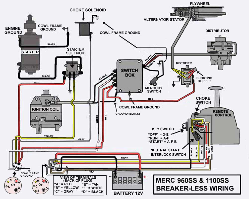
The ignition wiring diagrams illustrate the different wires used to are used to power various components of the vehicle. There are usually four terminals with color codes that are connected to the respective component. The red color is used for accessories while yellow is the battery, and green is for the starter solenoid. The “IGN” terminal lets you start your car, operate the wipers, or any other features that operate. The diagram below shows how to connect both the ACC terminal as well as the ST terminals to the other components.
The terminal referred to as BAT is where the battery is connected. Without the battery the electrical system will not begin. Furthermore the switch isn’t turned on. If you don’t know the exact location where the battery in your car is situated, look at your wiring diagram to see how to locate it. The accessory terminals of your car are connected to the battery as well as the ignition switch. The BAT terminal connects to the battery.
Some ignition switches come with an additional “accessory” position, in which users can manage their outputs without using the ignition. Sometimes, customers want to make use of the auxiliary output separate from the ignition. You can utilize the secondary input by connecting the connector to the ACC terminal. This is a great feature, but there is an important difference. The majority of ignition switches have an ACC position when the vehicle is in the ACC however, they’ll be in the START position when the vehicle is in IGN.
Gallery of Mercury Thunderbolt Ignition Wiring Diagram
Gallery of Mercury Thunderbolt Ignition Wiring Diagram


