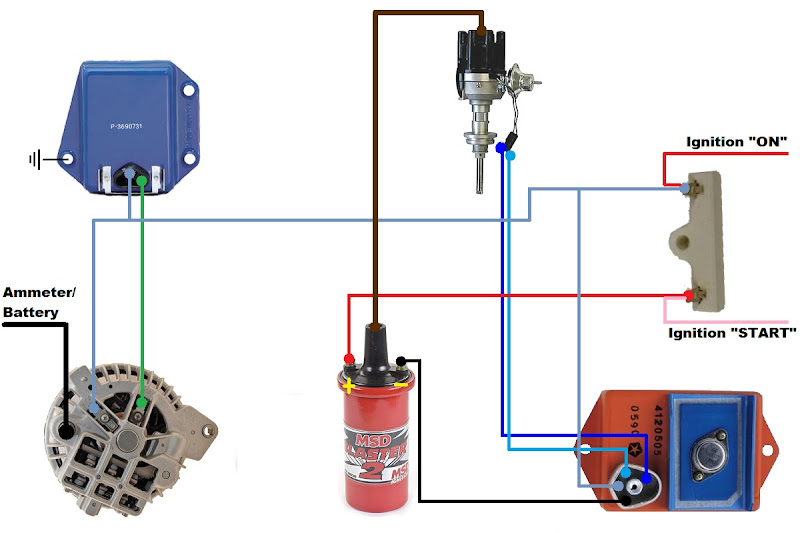
Mopar Electronic Ignition Conversion Wiring Diagram – First, we will take a look at the various kinds of terminals that are found in the ignition switch. These terminals are used for the Ignition button, Coil and Accessory. Once we understand the function of each terminal, we are able to identify the parts of the ignition wiring. We’ll also discuss the functions of both the Ignition Switch and Coil. We will then concentrate on the accessory terminals.
Terminals for ignition switches
There are three different switches on an ignition switch, which provide the battery’s voltage to a variety of locations. The first switch powers the choke. The third switch regulates the ON/OFF switch of the ignition switch. Different manufacturers have different colour-coding systems that correspond to the conductors. OMC follows this method. Connectors can be connected to the ignition switch in order to include the digital tachometer.
While most ignition switch terminals can be duplicated, the numbers might not be consistent with the diagram. You should first check the continuity of the wires to ensure that they are connected to the ignition switch in the correct way. You can do this with a simple multimeter. When you’re satisfied with the continuity of your wires, you will be able to install the new connector. If your vehicle has an ignition switch that is installed the wiring diagram may differ.
It is important to understand how the ACC outputs and auxiliary outputs function in order to connect them. The ACC/IGN connections function as the default connections for the ignition switch. The START/IGN connections connect to the radio or stereo. The ignition switch turns the car’s engine on and off. On older vehicles, the ignition switch terminals are marked with the initials “ACC”, and “ST” (for distinct magnet wires).
Coil terminals
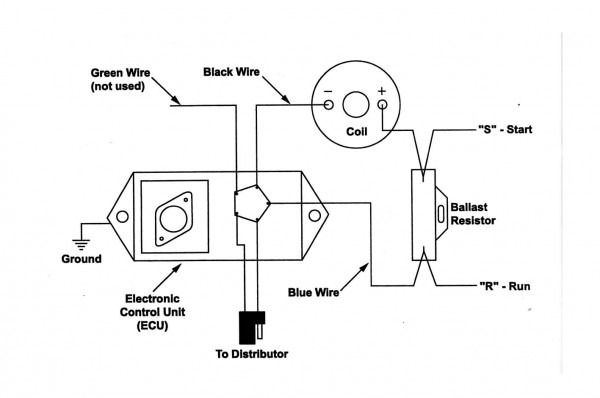
Understanding the terminology that is used is the initial step towards determining the kind of ignition coil you need. The fundamental diagram of ignition wiring depicts various connections and terminals. There are two primary and one secondary. You must determine the type of coil that you have by testing the voltage on the primary terminal S1. To determine if the coil is a Type A, C, or B coil you should also check the resistance of S1.
The coil’s low-tension side must be connected with the chassis’ positive. This is what is known as the ground for the wiring for ignition. The high-tension supply provides the spark plugs with positive electricity directly. To prevent noise, the coil’s metal body must be connected to chassis. But, it’s not necessary to electrically connect. The wiring diagram for ignition will also indicate the connections of the positive coil’s terminals. Sometimes, a malfunctioning ignition coil is identified by a scan done at an auto repair shop.
The black-and-white-striped wire from the harness goes to the negative terminal. The positive terminal also gets the white wire that includes a black trace. The black wire connects to the contact breaker. It is possible to check the connections with a paperclip to remove the wires of the housing. Be sure that the terminals aren’t bent.
Accessory terminals
Diagrams of the ignition wiring illustrate the wires used to supply power to different parts of the car. There are typically four colors of terminals connected to each part. Red is used for accessories, yellow is for the battery, and green is for the solenoid for starters. The “IGN” terminal is used for starting the car, operating the wipers and other functions. The following diagram shows how to connect the ACC terminal and ST terminals to the other components.
The terminal BAT is the connector for the battery. The battery is necessary to allow the electrical system to begin. In addition, the switch will not start. If you’re not sure where your car’s battery is located, you can review your wiring diagram to see how to locate it. The ignition switch is connected to the car’s battery. The BAT terminal is connected to the battery.
Some ignition switches come with an accessory position. This lets users connect their outputs to a different place without having to turn on the ignition. Customers sometimes want an auxiliary output that can be used separately from the ignition. Make use of the secondary output by connecting it to the ACC terminal on your switch that has the same color. Although this is a useful feature, there is one important difference. The majority of ignition switches are set to be in an ACC position when the car is in the ACC position, whereas they’re in the START position when the car is in the IGN position.
Gallery of Mopar Electronic Ignition Conversion Wiring Diagram
Gallery of Mopar Electronic Ignition Conversion Wiring Diagram


