Motorcycle Ignition Coil Wiring Diagram – We will first look at the different types of terminals that are found on the ignition switch. They include terminals for the Ignition switch, Coil, and Accessory. Once we’ve determined the function of the terminals we can determine the various components of the ignition wiring. We will also discuss the roles of the Ignition switch, as well as the Coil. Then, we’ll turn our attention to Accessory terminals.
Terminals for ignition switches

An ignition switch has three switches. They feed the voltage of the battery to different places. The first one supplies the choke with power when it is pushed. The second is the ignition switch’s ON/OFF position. Different manufacturers have different color-coding schemes to identify different conductors. We will cover this in a separate article. OMC follows this scheme. Connectors can be attached to the ignition switch in order to connect the digital tachometer.
While most ignition switch terminals can be duplicated, the number may not be in line with the diagram. You should first check the continuity of the wires to ensure that they are connected to the correct ignition switch. A simple multimeter will assist you in this. When you’re satisfied with the integrity of your wires, you will be able to connect the new connector. If your car is equipped with an original factory-supplied ignition switch (or wiring loom) The wiring loom will differ from the one in your vehicle.
Knowing how the ACC outputs connect to the other outputs of your vehicle is crucial. The ACC terminals and IGN terminals function as the default connections to the ignition switch. The START and IGN connections are the most important connections for stereo and radio. The ignition switch turns the car’s engine ON and OFF. The terminals of the ignition switch on older cars are identified with the letters “ACC” as well as “ST” (for the individual magneto wires).
Terminals for coil
Understanding the terminology that is used is the initial step in determining what kind of ignition coil you need. There are a variety of connections and terminals within the basic wiring diagram for ignition that include two primary as well as two secondary. Each coil operates at a specific voltage. The first step to determine which type you’re using is to examine the voltage at S1 or the primary terminal. To determine if the coil is an A, C or B coil, you should also test S1’s resistance.
The low-tension end of the coil needs to be connected to the chassis’ negative. It is also the ground on the diagram of ignition wiring. The high-tension part provides positive direct to the sparkplugs. To prevent noise the coil’s metal body must be connected to the chassis. It’s not necessary to use electricity. The wiring diagram will depict the connection between positive and negative coil terminals. Sometimes, a check at an auto part store can identify a problem with the ignition wire.
The black-and-white-striped wire from the harness goes to the negative terminal. The white wire is the other one. It is black with a trace on it, and it connects to the positive terminal. The black wire connects to the contact breaker. It is possible to check the connections with a pencil to take the wires out of the housing. Also, make sure to ensure that the terminals haven’t been bent.
Accessory terminals
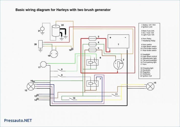
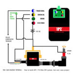
Diagrams of ignition wiring illustrate the wiring used to power various parts of the car. There are generally four colored terminus lines for each component. Red stands for accessories, yellow for the battery, and green for the solenoid for starters. The “IGN” terminal is used to turn on the car, operate the wipers, as well as other functions. The diagram demonstrates how to connect the ACC and ST terminals to the rest of the components.
The terminal known as BAT is where the battery is connected. The battery is essential for the electrical system to get started. The switch will not turn on if the battery isn’t present. It is possible to view the wiring diagram of your car to see where the batteries of your car are located. The ignition switch as well as the battery are connected through the accessory terminals. The BAT terminal is connected to the battery.
Some ignition switches have an “accessory” position that allows users to regulate their outputs without needing to turn on the ignition. Some customers want the auxiliary output to be used independently from the ignition. In order for the auxiliary output be used, connect the connector in the same color as the ignition. Connect it to the ACC end of the switch. While this is an excellent option, there’s an significant difference. The majority of ignition switches are designed to show an ACC status when the car is at the ACC or START positions.
Gallery of Motorcycle Ignition Coil Wiring Diagram
Gallery of Motorcycle Ignition Coil Wiring Diagram


