Msd Ignition 6al 6420 Wiring Diagram – We will first take a look at the various kinds of terminals found on the ignition switch. These terminals serve for the Ignition button, Coil and Accessory. Once we have identified what these terminals are, we will identify the different parts in the ignition wiring. In addition, we will discuss the function of the Ignition switch and Coil. Then, we will turn our attention towards the accessory terminals.
The terminals of the ignition switch
The ignition switch consists of three different switches. They are responsible for supplying the battery’s energy to various destinations. The choke is powered by the first switch. The second switch is responsible for the ON/OFF function of the ignition switch. Different manufacturers use different color-coding methods to identify different conductors. We will cover this in another article. OMC uses the same method. An adapter is included on the ignition switch that allows the installation of the tachometer.
Although the majority of ignition switch terminals don’t come in original form however, the numbers may not be in line with the diagram. Before plugging in the ignition switch, be sure to test the continuity. You can do this with a simple multimeter. Once you’re satisfied about the integrity of your wires, you’ll be able to install the new connector. If your car is equipped with an original factory-supplied ignition switch (or an electrical loom), the wiring loom may differ from that in the car.
To connect the ACC outputs to the auxiliary outputs on your car, you’ll need first know how these two connections work. The ACC/IGN terminals act as the default connection on the ignition switch. The START/IGN terminals connect to the stereo or radio. The ignition switch turns the car’s engine ON and OFF. Older cars have the ignition switch terminals labeled “ACC” or “ST” (for individual magnetowires).
Terminals for coil
The first step in determining the type of ignition coil is to know the terms employed. A basic ignition wiring diagram will show a variety of terminals and connections, including two primary and two secondary. You need to determine the type of coil you have by testing the voltage on the primary terminal S1. To determine if the coil is a Type A, C or B coil, you should also test S1’s resistance.
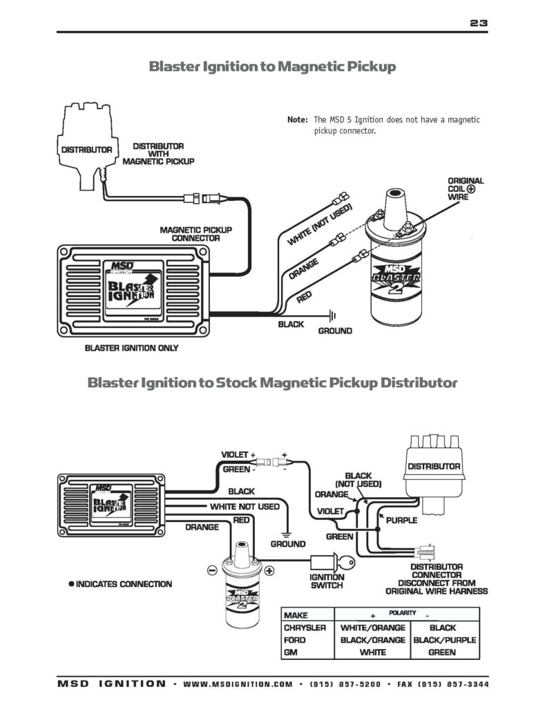
The coil with low tension must be connected at the chassis’ less. This is exactly what you can find in the diagram of wiring. The high-tension part is a positive connection to the sparkplugs. The coil’s aluminum body needs to be connected to the chassis for suppression however it’s not electrically required. The wiring diagram for the ignition will explain how to connect the terminals of the positive or negative coils. Sometimes, a check at an auto parts store could identify a problem with the ignition wire.
The black-and-white-striped wire from the harness goes to the negative terminal. The positive terminal also receives a second white wire, which is black in its trace. The black wire connects to the contact breaker. If you’re not certain about the connections of the twowires, use the clip of a paperclip to remove them from the housing of the plug. It is also important to ensure that the terminals aren’t bent.
Accessory Terminals
Diagrams of ignition wiring illustrate the wires that provide power to various components of the car. There are usually four different colors of terminals connected to each part. Red refers to accessories, yellow is the battery, and green the starter solenoid. The “IGN” terminal can be used to start the car , and also to operate the wipers, as well as other operating features. This diagram shows how to connect ACC and ST terminals with the rest of components.
The terminal BAT is the connection to the battery. The electrical system will not start if the battery isn’t connected. The switch also won’t start without the battery. The wiring diagram will inform you the location of the battery in your car. The ignition switch and the battery are connected via accessory terminals. The BAT connector is connected to the battery.
Some ignition switches come with an additional “accessory position” that lets users modify their outputs independent of the ignition. Sometimes, customers wish to utilize the auxiliary output separately from the ignition. The auxiliary output could be used to connect the connector in the same color as your ignition and attaching it to the ACC terminal of the switch. This is a convenient feature, but it has one significant distinction. Most ignition switches come with the ACC position when the car is in the ACC mode, and a START position when the switch is in IGN.
Gallery of Msd Ignition 6al 6420 Wiring Diagram
Gallery of Msd Ignition 6al 6420 Wiring Diagram


