Msd Streetfire Ignition Box Wiring Diagram – First, we will take a look at the various kinds of terminals found on the ignition switch. These terminals serve for the Ignition button, Coil and Accessory. Once we know the purpose of these terminals are for, we will proceed to determine the various parts of the Msd Streetfire Ignition Box Wiring Diagram. We will also talk about the functions as well as the Coil. The next step is to focus on the accessory terminals.
Terminals for ignition switch
The ignition switch is comprised of three switches that supply the battery’s current to different destinations. The first switch supplies the choke with power, and the third switch toggles the ON/OFF state of the switch. Different manufacturers use their own color-coding systems for the different conductors, which is documented in another article. OMC utilizes this method. An additional connector is included inside the ignition switch for connecting the tachometer.
Although the majority of ignition switch terminals can be duplicated, the numbers may not be consistent with the diagram. Before plugging in the ignition switch, make sure to check the continuity. This can be done using a cheap multimeter. After you’re happy with the integrity of your wires, you’ll be able install the new connector. If your car has an original ignition switch supplied by the factory (or an electrical loom) The wiring loom may differ from that of your car.
Understanding how the ACC outputs connect to the auxiliary outputs inside your car is essential. The ACC and IGN terminals are the default connection on the ignition switch. the START and IGN terminals are the principal connections to the stereo and radio. The ignition switch is the one that turns the car’s engine on and off. On older vehicles, the ignition switch terminals are marked with the letters “ACC” and “ST” (for individual magnetic wires).
Terminals for coil
The first step in determining the type of ignition coil is to understand the terms used. An ignition wiring diagram will show a variety of terminals and connections, which include two primary terminals and two secondaries. The voltage that operates on each coil is different. This is why it is essential to first check the voltage at S1 (primary terminal). S1 should also be tested for resistance in order to identify if it’s an A, Type B, or an A coil.
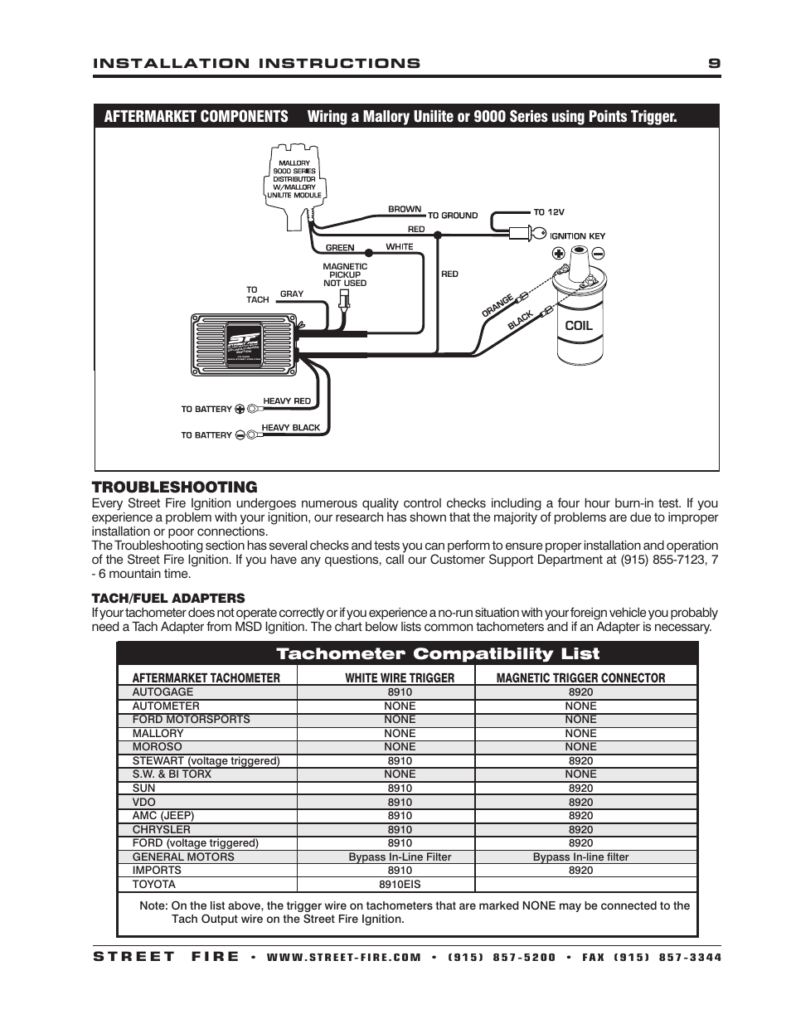
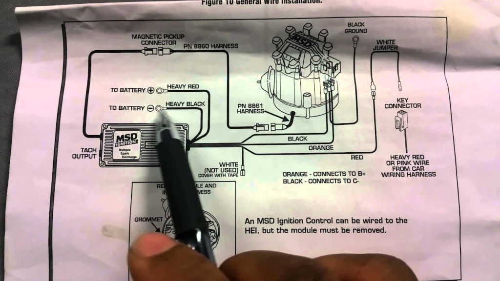
The chassis’ negative end should be connected to connect the coil’s low-tension side. This is what you see in the diagram of wiring. The high-tension component supplies the positive power direct to the spark plugs. The metal body of the coil needs to connect to the chassis for suppression purposes, but it is not electrically necessary. A wiring diagram can also illustrate the connection between the positive and negative coil terminals. Sometimes, a malfunctioning ignition coil is identified by a scan done at an auto parts shop.
The black-and-white-striped wire from the harness goes to the negative terminal. The terminal that is negative is served by the trace in black that’s joined to the white wire. The black wire connects to the contact breaker. You can check the connections using a paperclip to pull the wires out from the housing. Make sure that the connectors aren’t bent.
Accessory Terminals
Diagrams of ignition wiring illustrate the wiring used in the vehicle’s power supply. There are usually four color-coded terminals that correspond to the respective component. Red refers to accessories, yellow the battery and green the starter solenoid. The “IGN” terminal is used to start the car, operate the wipers and other functions. The diagram illustrates the connection between the ACCand ST terminals.
The battery is attached to the terminal named BAT. Without the battery the electrical system will not begin. A dead battery can make the switch stop turning on. If you don’t know the location of your car’s battery located, you can look at the wiring diagram of your car to determine the best way to find it. The ignition switch is connected to the battery of your car. The BAT terminal connects to the battery.
Some ignition switches feature an “accessory” position that allows users to regulate their outputs without needing to turn on the ignition. Users may wish to use the auxiliary output separately from the ignition. In order to use the auxiliary output, connect the connector in the same colors as the ignition connecting it to the ACC terminal on the switch. This convenience feature is great however, there’s one difference. Most ignition switches will be in an ACC position when the vehicle is in the ACC, but they will be in the START position if the vehicle is IGN.
Gallery of Msd Streetfire Ignition Box Wiring Diagram
Gallery of Msd Streetfire Ignition Box Wiring Diagram


