Pazon Ignition Wiring Diagram – In the beginning, we’ll look at the different types of terminals found on the ignition switch. These are the terminals that connect the Ignition, Coil, or Accessory. After we’ve identified the terminals that are utilized then we can recognize the various parts of the Pazon Ignition Wiring Diagram. We will also talk about the functions as well as the Coil. Then we’ll discuss the Accessory Terminals.
Terminals for ignition switches
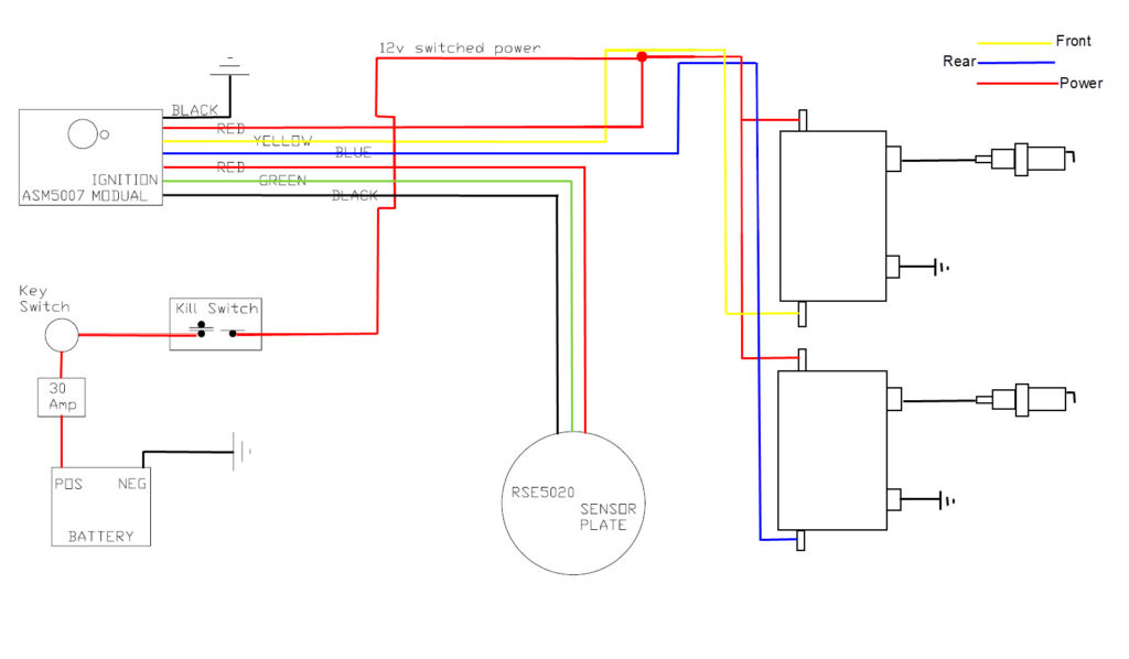
An ignition switch is made up of three switches. These are the ones that supply the battery’s power to several locations. The ON/OFF setting of the ignition switch is controlled by the first switch, which supplies the choke with power when it’s pulled. Different manufacturers have different colors for different conductors. This is discussed in a separate article. OMC uses this procedure. The ignition switch comes with an option to connect an timer.
Even though some ignition switch terminals do not have the original design The numbering might not match that of the diagram. To make sure that your wires are connected to the switch it is recommended to check their continuity. A multimeter that is inexpensive can help you do this. Once you are satisfied with the integrity of the wires you can install the new connector. The wiring loom of the ignition switch supplied by the factory will be different from the one you have in your car.
First, understand the differences between the ACC and secondary outputs. The ACC and IGN terminals are the default connection on your ignition switch. the START and IGN terminals are the principal connections for stereo and radio. The ignition switch is the one that controls the engine of your car. Older cars are equipped with ignition switch’s terminals that are labeled “ACC” or “ST” (for individual magnetowires).
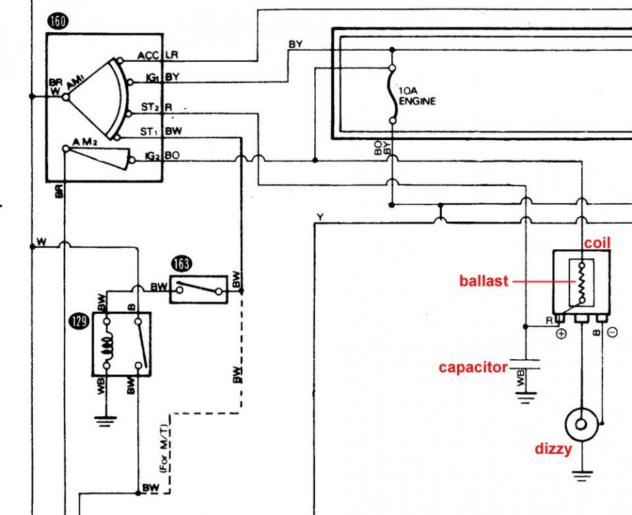
Terminals for coil
Understanding the terms is the initial step in finding out what kind of ignition coil you own. An ignition wiring diagram will show a variety of connections and terminals, which include two primary terminals and two secondary. The coils have a specific operating voltage. The initial step to determine which one you’ve got is to check the voltage of S1 the primary terminal. To determine if the coil is a Type A, C or B coil, you should also test S1’s resistance.
The coil with low tension must be connected to the chassis’ less. This is what is known as the ground for the ignition wiring. The high-tension supply provides the spark plugs with positive electricity directly. For suppression purposes the coil’s body metal must be connected to the chassis. It is not required to use electricity. You will also see the connections between the positive and the negative coil’s terminals on the diagram of the ignition wiring. Sometimes, a defective ignition coil can be identified with a scan in an auto parts shop.
The black-and-white-striped wire from the harness goes to the negative terminal. The negative terminal is served by the trace in black that’s joined to the white wire. The black wire goes to the contact breaker. You can examine the connections with a pencil to pull the wires out of the housing. It is also important to make sure that the terminals don’t bend.
Accessory Terminals
The ignition wiring diagrams illustrate the various wires used to power the car’s various components. There are generally four color-coded terminals that correspond to each component. To identify accessories, red is for starter solenoid, yellow is for battery, and blue for accessory. The “IGN” terminal can be used to start the car , and also to operate the wipers as well as other operational functions. This diagram shows how to connect ACC and ST terminals to the other components.
The terminal BAT is where the battery is. The electrical system won’t start in the event that the battery isn’t connected. A dead battery could cause the switch to not turn on. To find your car’s battery look over your wiring diagram. The accessory terminals in your vehicle are connected to the battery and the ignition button. The BAT Terminal is connected to the Battery.
Some ignition switches come with an accessory position. It allows users to connect their outputs to a different location without having to turn on the ignition. Sometimes, customers want to use an auxiliary output that is independent of the ignition. You can use the auxiliary input by connecting it to the ACC terminal. While this is an excellent feature, there’s one thing you need to know. Most ignition switches are set up to display an ACC status when the car’s in either the ACC or START positions.
Gallery of Pazon Ignition Wiring Diagram
Gallery of Pazon Ignition Wiring Diagram


