Piranha Ignition Wiring Diagram – We will first look at the various types and purposes of the terminals that are found on the ignition switches. These include the terminals for the Ignition switch, Coil, and Accessory. Once we’ve determined the function of these terminals, we will be able to determine the various components of the ignition wiring. In addition, we will discuss the functions of both the Ignition Switch and the Coil. After that, we’ll turn our attention to Accessory terminals.
Terminals for ignition switch
There are three different switches on the ignition switch, and they provide the battery’s voltage to a variety of places. The ON/OFF setting of the ignition switch is controlled by the second switch, which supplies power to the choke when it is pushed. Different manufacturers employ different colors for different conductors. This is described in a different article. OMC follows this scheme. The adapter is attached to the ignition switch, allowing the installation of an tachometer.
Although the majority of ignition switch terminals don’t carry an original number, they may have a different number. Before you plug in the ignition switch, ensure that you check the continuity. This can be checked using an inexpensive multimeter. After you’re sure that all wires are in good continuity and you are able to connect the new connector. The wiring loom in a factory-supplied ignition system switch is different.
To connect the ACC outputs to the auxiliary outputs on your vehicle, you have first know how these two connections work. The ACC/IGN connections function as the default connection on the ignition switch. The START/IGN terminals are connected to the radio or stereo. The ignition switch switches the car’s engine on and OFF. The terminals of older cars ignition switches are marked with “ACC” and ST (for the individual magneto wires).
Terminals for coil
The first step to determine the type of ignition coil is to understand the terminology used. The basic ignition wiring diagram illustrates a variety of connections and terminals. There are two primary and secondary connections. The voltage that operates on each coil differs. This is why it is essential to first check the voltage at S1 (primary terminal). You should also check S1 for resistance in order to identify if it’s an A or B coil.
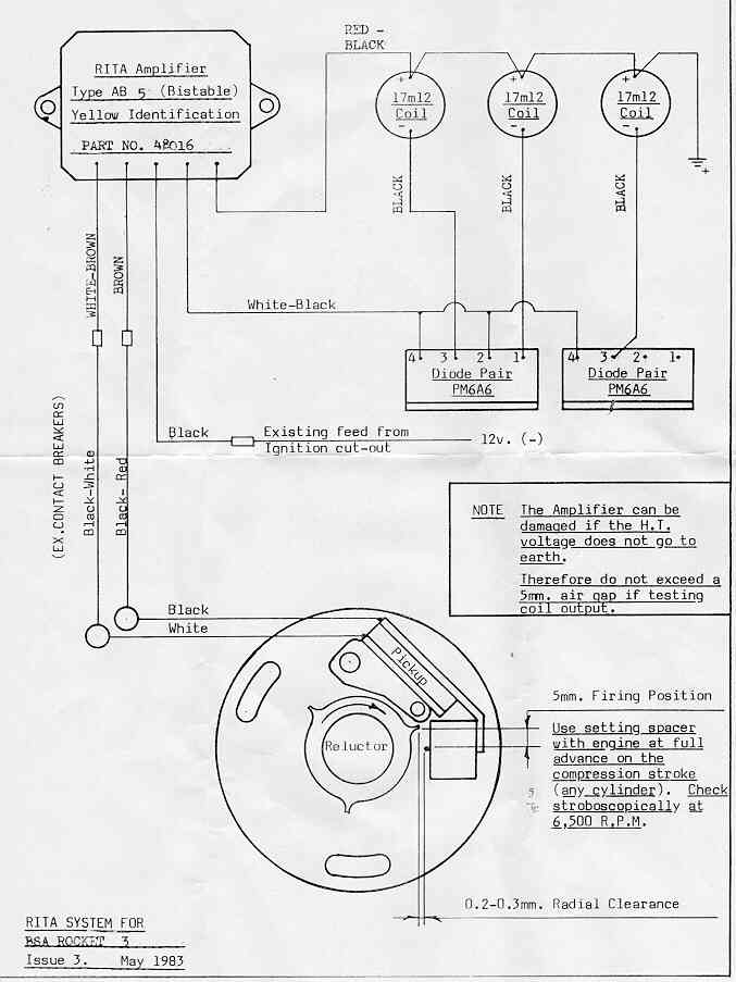
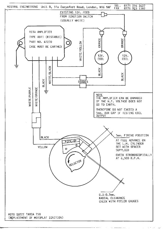
The low-tension coil side must be connected at the chassis’s plus. This is the ground in the wiring diagram for ignition. The high-tension side delivers positively direct to the spark plugs. For suppression purposes the coil’s body metal must be connected to the chassis. It’s not necessary for electrical use. The wiring diagram for the ignition will demonstrate how to connect the two terminals of the positive and negative coils. Sometimes, an inspection at an auto part store can diagnose a malfunctioning ignition wire.
The black-and-white-striped wire from the harness goes to the negative terminal. The terminal for the negative is served by the black trace attached to the white wire. The contact breaker is connected to the black wire. You can check the connections with a pencil to remove the wires from the housing. It’s also essential to make sure that the terminals aren’t bent.
Accessory terminals
The wiring diagrams of the ignition illustrate the different wires that are used to power various components of the car. There are typically four terminals with color codes that are connected to the respective component. Red is used for accessories, yellow is for the battery, and green is the starter solenoid. The “IGN terminal” is used to power the wipers and other operating functions. This diagram shows how to connect ACC and ST terminals with the other components.
The terminal called BAT is the location where the battery is. Without the battery the electrical system will not get started. A dead battery can cause the switch to stop turning on. It is possible to refer to your wiring diagram if not sure where the batteries of your car are. The ignition switch as well as the battery are connected by the accessory terminals. The BAT Terminal is connected to the Battery.
Certain ignition switches have an accessory position. It allows users to connect their outputs to a different place without having to turn on the ignition. Customers may want to use the auxiliary output independently of the ignition. You can utilize the additional input by connecting it to the ACC terminal. This is a useful feature, but there is one important difference. Most ignition switches will have an ACC position when the vehicle is in the ACC, but they’ll be at the START position if the vehicle is IGN.
Gallery of Piranha Ignition Wiring Diagram
Gallery of Piranha Ignition Wiring Diagram


