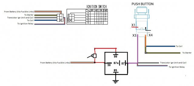
Points Ignition Coil Wiring Diagram – We’ll begin by looking at the different types of terminals on an ignition switch. These terminals are used for the Ignition button, Coil and Accessory. After we’ve established the purpose of these terminals are for then we can identify the different parts of the Points Ignition Coil Wiring Diagram. We will also discuss the functions of the Ignition switch and Coil. After that we will move on to the Accessory Terminals.
Terminals for ignition switches
The ignition switch consists of three switches. They are responsible for feeding the battery’s energy to various locations. The first one supplies power to the choke when pushed, and the second is the ignition switch’s ON/OFF position. Every manufacturer has its own color-coding system, which we’ll discuss in a subsequent article. OMC uses the same method. A connector can be added to the ignition switch to add the digital Tachometer.
Although many ignition switch terminals don’t come in original form The numbering might not be in line with the diagram. It is important to first verify the electrical continuity to see if they are plugged into the ignition switch correctly. This can be done with a multimeter that is inexpensive. After you’ve confirmed that the wires are in good condition, you are able to install the connector. If your vehicle has an original factory-supplied ignition switch (or wiring loom) the wiring loom may differ from the one in the car.
You must first understand how the ACC outputs and auxiliary outputs function in order to join them. The ACC/IGN terminals function as the default connections for the ignition switch. The START/IGN terminals are connected to the radio or stereo. The ignition switch is the one that turns the engine of your car on and off. Older cars are equipped with ignition switch’s terminals that are labeled “ACC” or “ST” (for individual magnetowires).
Coil terminals
Understanding the terms is the initial step towards knowing what type of ignition coil you have. A basic diagram of the wiring will show you a number of terminals and connections. Each coil has a specific operating voltage. To determine the type of coil you’ve got, the first step is to test the voltage at S1, which is the primary terminal. S1 should also be checked for resistance in order to identify whether it’s an A, Type B or A coil.
The coil with low tension must be connected to the chassis’ minus. This is what you find in the wiring diagram. The high-tension part provides positive direct to the sparkplugs. For suppression purposes, the coil’s metal body must be connected to chassis. But, it’s not necessary to connect the coil electrically. The wiring diagram will also illustrate the connection between the positive and negative coils. Sometimes, a damaged ignition coil is identified through a scan performed at an auto parts shop.
The black-and-white-striped wire from the harness goes to the negative terminal. The white wire also has a black trace, and it connects to the positive terminal. The black wire is connected to the contact breaker. You can examine the connections with a pencil to remove the wires of the housing. Also, make sure to ensure that the terminals have not been bent.
Accessory terminals
The wiring diagrams of the ignition illustrate the different wires that power the various components of the vehicle. There are generally four color-coded terminals to each component. Red refers to accessories, yellow the battery, and green the starter solenoid. The “IGN” terminal is used to start the car, control the wipers and other features. This diagram shows how to connect ACC and ST terminals to the rest of the components.
The terminal BAT is where the battery is. The battery is essential to allow the electrical system to get started. Furthermore, the switch won’t begin to turn on. To find the battery in your car examine the wiring diagram. Your car’s accessory terminals are connected to the ignition switch as well as the battery. The BAT terminal is connected to the battery.
Some ignition switches have an “accessory” setting that permits users to regulate their outputs without needing to turn on the ignition. Some customers might want to utilize the auxiliary input independently of the ignition. You can use the secondary input by connecting the connector to the ACC terminal. This convenience feature is great however, there’s one distinction. Most ignition switches are configured to operate in the ACC position when the vehicle is in the ACC position, while they’re set to the START position when the vehicle is in the IGN position.
Gallery of Points Ignition Coil Wiring Diagram
Gallery of Points Ignition Coil Wiring Diagram


