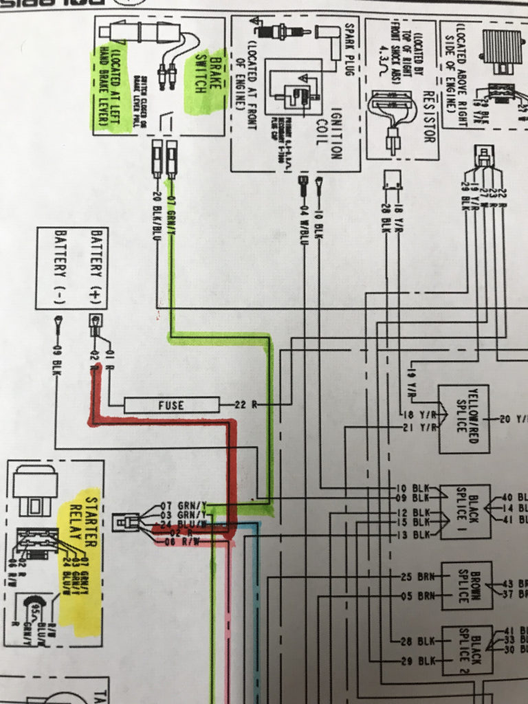
Polaris Sportsman Ignition Switch Wiring Diagram – First, we will take a look at the different kinds of terminals that are used on the ignition switch. These are terminals for the Ignition, Coil, or Accessory. Once we know which terminals are used and which ones are not, we can recognize the various parts of the Polaris Sportsman Ignition Switch Wiring Diagram. We’ll also go over the roles of the Ignition switch as well as the Coil. Following that, we will move on to the Accessory Terminals.
Terminals for the ignition switch

The ignition switch is comprised of three separate switches that feed the battery’s power to various locations. The first one is used to power the choke by pushing it. Then, the second is for the ON/OFF position. Different manufacturers utilize their own color-coding method for the different conductors, that is described in a separate article. OMC follows this method. An adapter is included on the ignition switch, allowing the installation of a tonometer.
Although some ignition switch terminals may not be authentic, the numbering of each may not match the diagram. Check the electrical continuity first to ensure that they are correctly plugged in the ignition switch. A simple multimeter will help you do this. After you’re happy with the integrity of the wires, then you’ll be able install the new connector. The wiring loom for an ignition switch that’s supplied by the manufacturer will differ from the one in your car.
The first step is to understand the distinctions between the ACC and the auxiliary outputs. The ACC and IGN connectors are the default connections of the ignition switch. Although the START, IGN, and ACC terminals are the primary connections for radios or stereo, the START/IGN connections are the primary ones. The ignition switch is the one that turns the engine of your car to and off. On older cars the terminals of the ignition switch are identified with the alphabets “ACC”, and “ST” (for individual magnetic wires).
Terminals for coil
To identify the kind of ignition coil you need to know the step is to learn the terminology. In a basic ignition wiring diagram you’ll see various connections and terminals, such as two primary and two secondary. The operating voltage of every coil is different. This is why it is essential to first check the voltage at the S1 (primary terminal). It is also recommended to check S1 for resistance in order to determine if it’s a Type A, B, or C coil.
The coil’s low-tension end must be connected with the chassis positive. This is the base of the ignition wiring. The high-tension side delivers the positive power directly to the spark plugs. To prevent noise the coil’s body metal must be connected with the chassis. It’s not necessary for electrical use. The ignition wiring diagram will also demonstrate the connections between the negative and positive coil terminals. You may find an issue with your ignition coil that can be easily diagnosed by scanning it at an auto parts store.
The black-and-white-striped wire from the harness goes to the negative terminal. The other white wire has a black trace on it and connects to the positive terminal. The contact breaker is linked to the black wire. It is possible to remove the black wire from the housing of the plug by using a paperclip If you’re unsure of the connections. Be sure to verify that the connections aren’t bent.
Accessory Terminals
Diagrams of ignition wiring show the various wires that are used for powering the different components. There are generally four terminals with color codes that are connected to the respective component. Red is for accessories and yellow is for the battery, while green is the starter solenoid. The “IGN terminal is used for starting the vehicle, controlling the wipers and other functions. The diagram demonstrates how to connect the ACC and ST terminals to the rest of the components.
The terminal BAT is where the battery is. The electrical system will not start without the battery. Additionally, the switch will not be able to turn on without the battery. To locate your car’s battery look over your wiring diagram. The ignition switch and battery are connected by the accessory terminals. The BAT terminal is connected to the battery.
Some ignition switches come with the option of an “accessory position” that allows users to alter their outputs without the ignition. Sometimes, customers wish to utilize the auxiliary output separate from the ignition. The auxiliary output could be used to connect the connector with the same color as your ignition and attaching it to the ACC terminal of the switch. This is a convenient feature however, it does have one significant difference. A lot of ignition switches can be programmed to have an ACC position once the car has been moved into the ACC position. They will also be in START mode once the vehicle is moved into the IGN position.
Gallery of Polaris Sportsman Ignition Switch Wiring Diagram
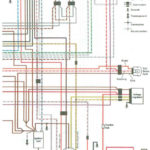
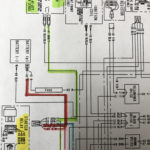
Gallery of Polaris Sportsman Ignition Switch Wiring Diagram


