Pollak Ignition Switch Wiring Diagram – Let’s start by looking at different types of terminals on an ignition switch. These terminals are used for the Ignition button, Coil and Accessory. Once we have identified what these terminals are then we can be able to identify the various parts of the ignition wiring. In addition, we will discuss the roles of both the Ignition Switch and Coil. The next step is to focus on the accessory terminals.
Terminals for the ignition switch
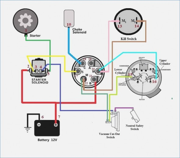
An ignition switch has three different switches that direct the battery’s power to various locations. The first switch powers the choke. The second switch is responsible for the ON/OFF of the ignition switch. Different manufacturers have different color-coding schemes for different conductors. This will be covered in a separate article. OMC follows the same system. The ignition switch comes with an adapter for the addition of the timer.
Although the majority of ignition switch terminals don’t carry an original number, they might have a different one. To ensure that your wires are properly plugged in to the switch, you should check their continuity. This can be done using an inexpensive multimeter. Once you are happy with the continuity of the wires you can connect the new connector. The wiring loom used in the ignition system switch supplied by the manufacturer is different.
Before connecting the ACC outputs to the auxiliary outputs of your car It is essential to be familiar with the fundamentals of these connections. The ACC/IGN terminals act as the default connection on the ignition switch. The START/IGN terminals connect to the radio or stereo. The ignition switch turns the engine of your car ON and OFF. The terminals for the ignition switch on older vehicles are marked with the initials “ACC” and “ST” (for each magneto wires).
Terminals for coil
The first step in determining the type of ignition coil is to comprehend the terms that is used. In a typical diagram of the wiring for ignition there are a number of different terminals and connections, including two primary and two secondary. The operating voltage of each coil is different. It is crucial to test the voltage at the S1 (primary terminal). S1 should also be tested for resistance in order to identify if it’s a Type B, B, or an A coil.
The chassis’ negative should be connected to the coil’s low-tension side. This is also the ground in the diagram of ignition wiring. The high-tension component supplies positive direct to the spark plugs. It is necessary for the purpose of suppression that the metallic body of the coil is connected to its chassis but not essential. The diagram for the ignition wiring will also show you the connections between the negative and positive coil terminals. In certain cases it is recommended to conduct a scan at your local auto parts shop can help you identify defective ignition coils.
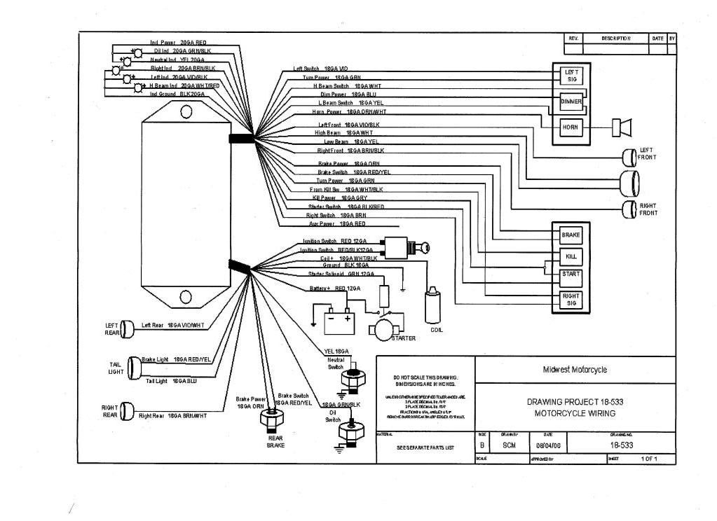
The black-and-white-striped wire from the harness goes to the negative terminal. The white wire has a black color and connects to the negative terminal. The black wire connects to the contact breaker. If you’re not certain about the connections of the twowires, use an old paper clip to take them from the plug housing. It’s also crucial to make sure that the terminals aren’t bent.
Accessory Terminals
The diagrams for ignition wiring show the wiring used in the power supply of the vehicle. Typically there are four colored terminals for each part. The red color represents accessories, yellow represents the battery, and green for the starter solenoid. The “IGN” terminal can be utilized to turn on the car, control the wipers, and other features. This diagram demonstrates how to connect ACC and ST terminals with the rest of components.
The battery is connected to the terminal called BAT. The electrical system can’t begin without the battery. A dead battery could make the switch not turn on. It is possible to refer to your wiring diagram if unsure where your car’s batteries are located. The accessory terminals of your car are connected to the ignition switch and the battery. The BAT connector connects to your battery.
Some ignition switches come with an independent “accessory” location, which allows users can manage their outputs with no ignition. Sometimes, customers may wish to use the auxiliary input separately from the ignition. In order for the auxiliary output be used, connect the connector with the same color as the ignition. Then , connect it to the ACC end of the switch. This is an excellent feature, however there’s one important distinction. Most ignition switches are set up to have an ACC status when the car’s at either the ACC or START positions.
Gallery of Pollak Ignition Switch Wiring Diagram
Gallery of Pollak Ignition Switch Wiring Diagram


